

 Tweet
Tweet
Excellent work Gunny
-
Len Buffinton
Team Horizon Hobby -
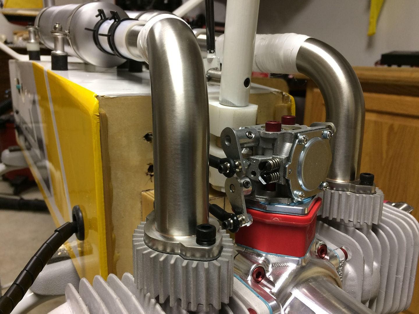
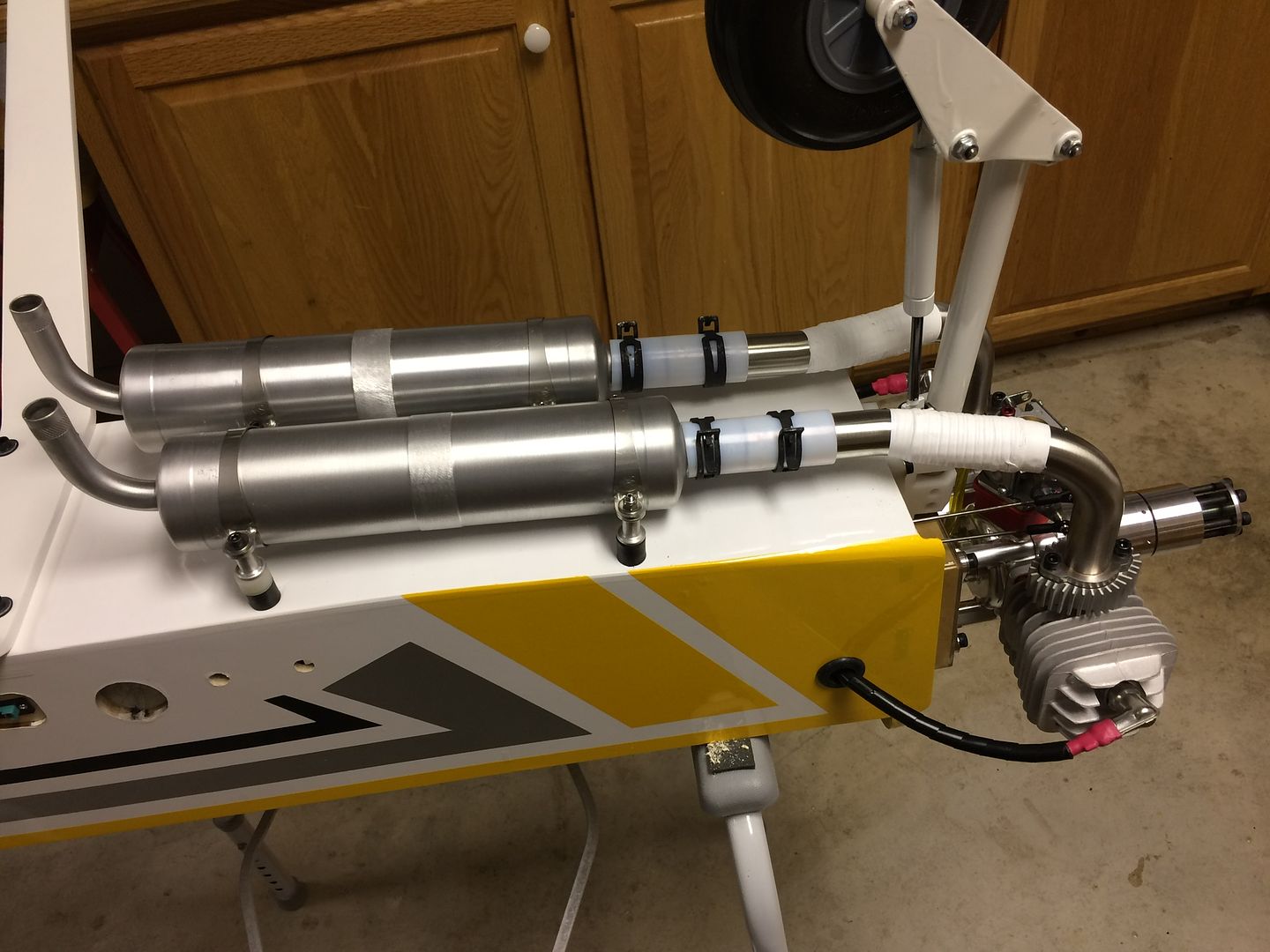
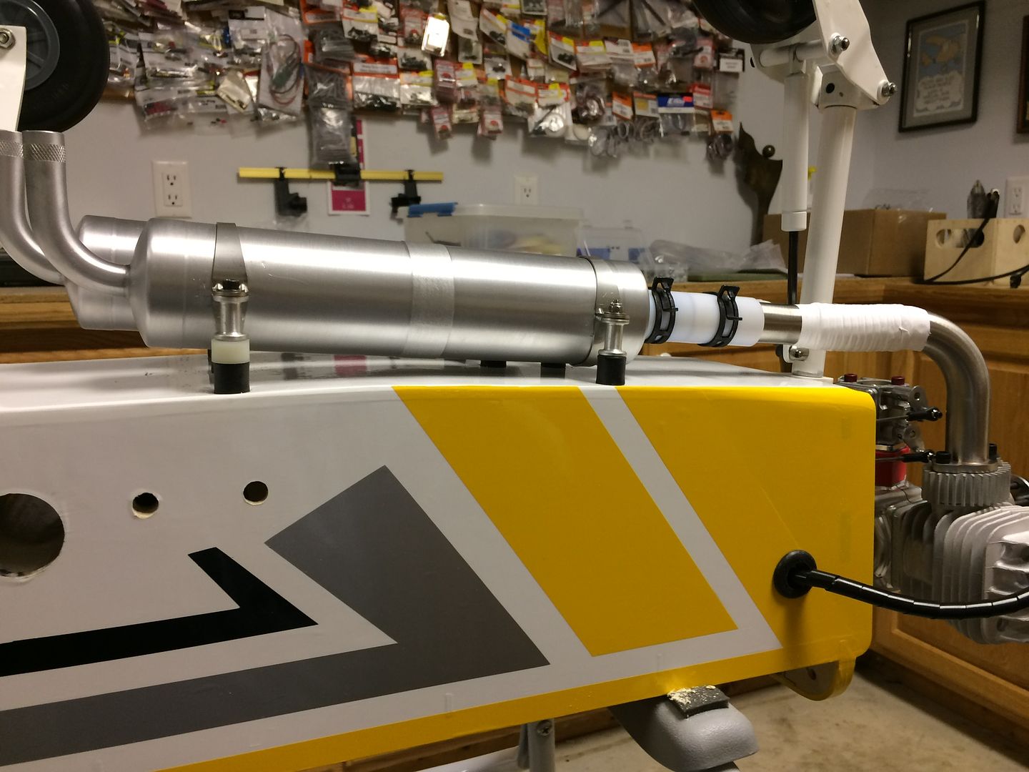
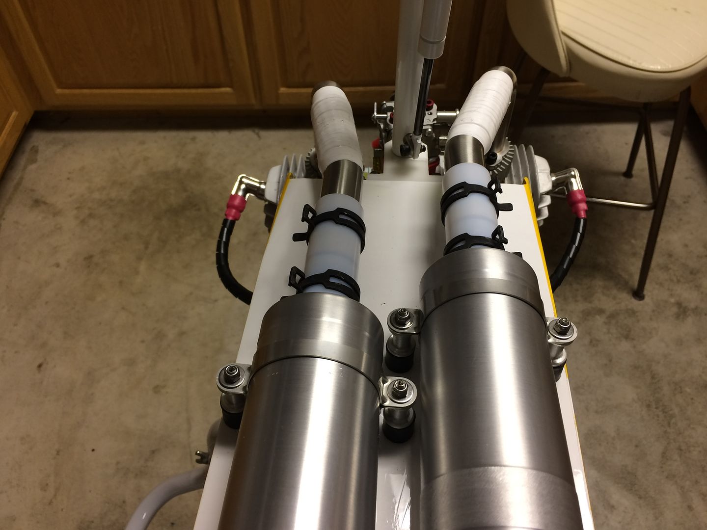
The extensions arrived today and worked exactly like I had hoped!
Thank you Gunny (Aviation Concepts)
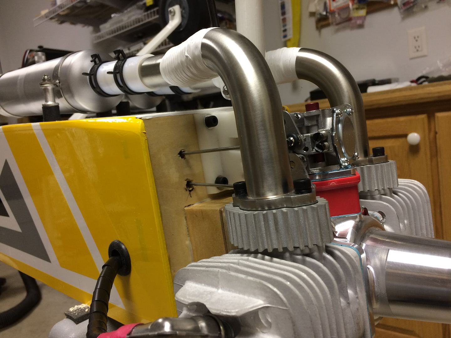
Everything lines up perfectly, no stress on any joint or canister mount.
 A Site for Soar Eyes
Comment
-
They look fabulous. I thought you were cutting the cowl today? eekLen Buffinton
Team Horizon HobbyComment
-
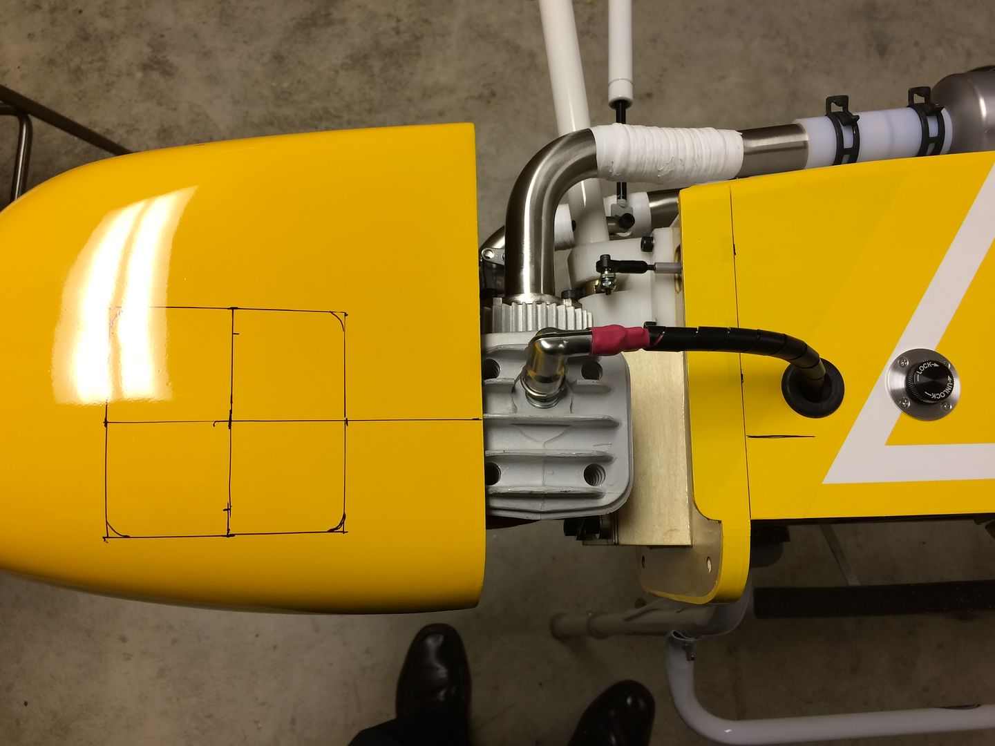
As promised, cowling cutting was on the agenda for today...Ugh...fiberglass dust!
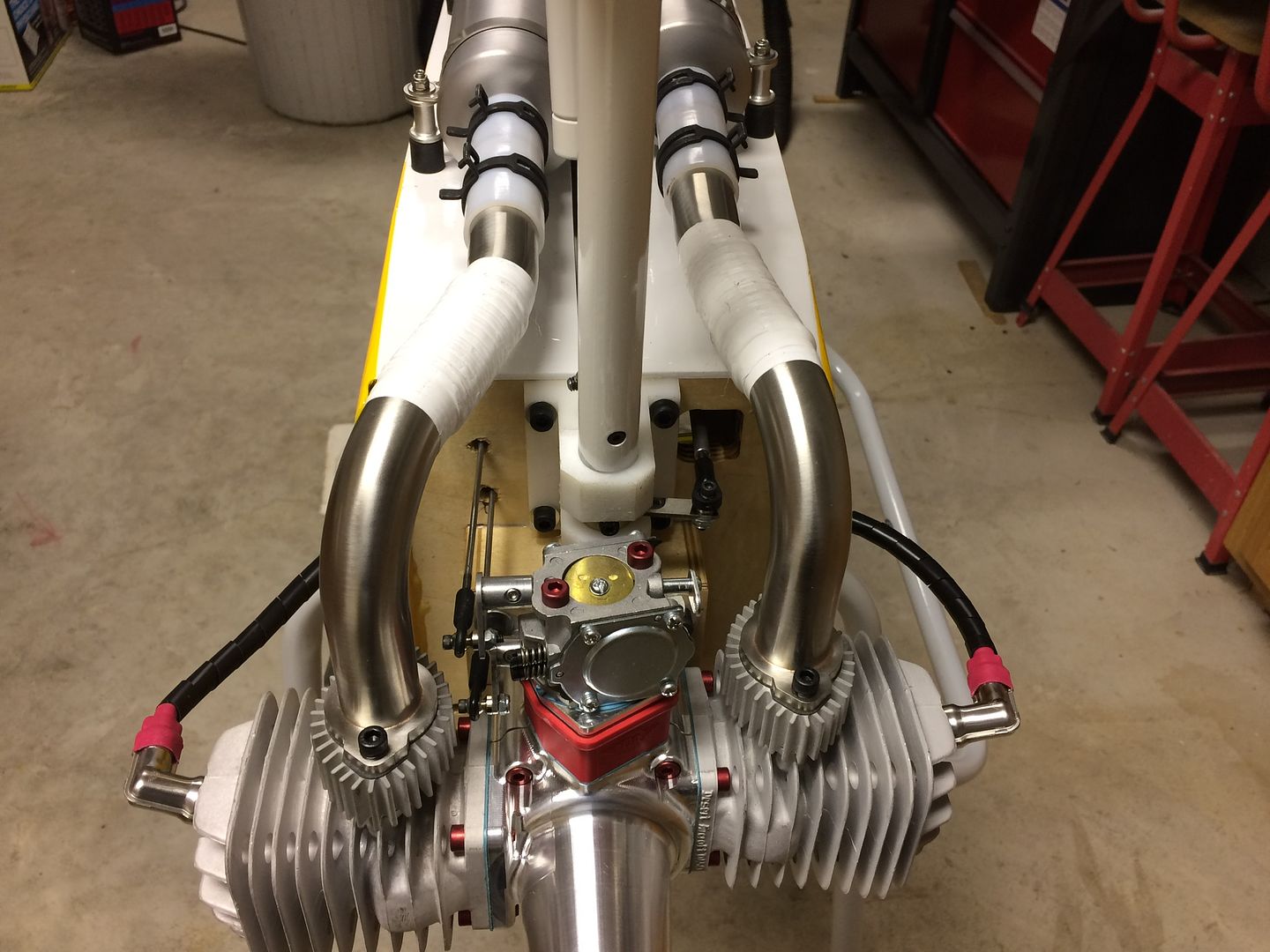
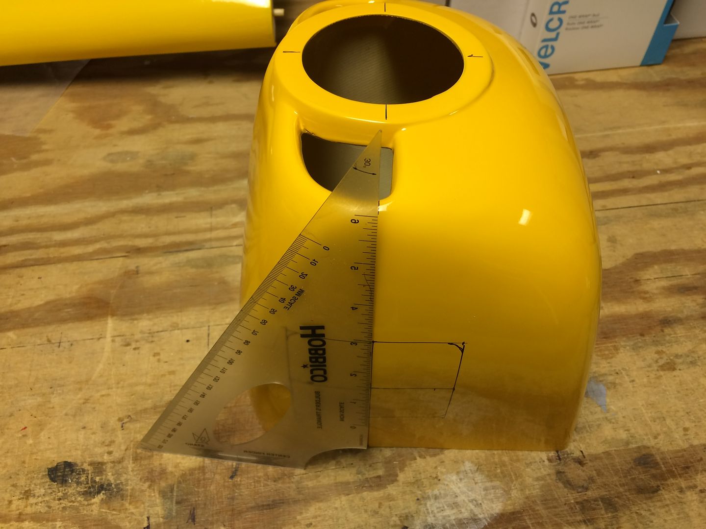
Time to get out the mask, gloves, long sleeve shirt, and vacuum. First thing was to find the center-line of each cylinder and mark it in reference to the back edge of the cowling location on the fuselage.

Then measuring from this reference, layout the opening for each cylinder.
Double check in reference to the center of the cowl spinner ring.
We drilled a 1/4" hole in the four corners and then used a Zona razor saw to cut between the holes.
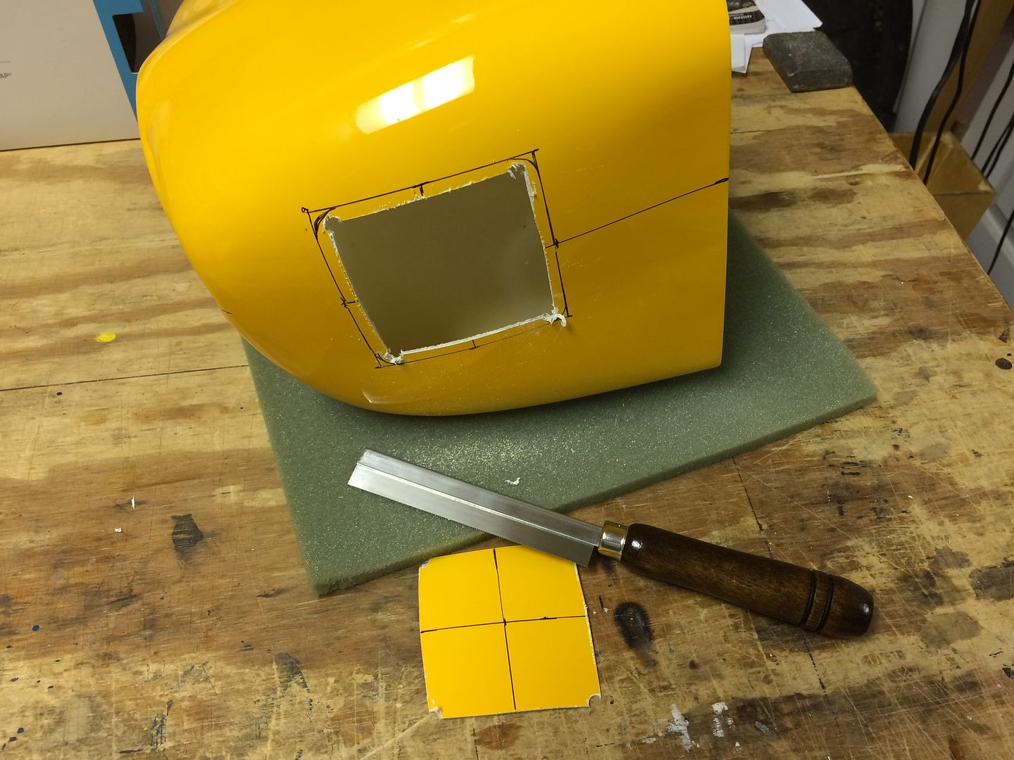
Then we used the Dremel tool with a sanding drum to dress the edges.
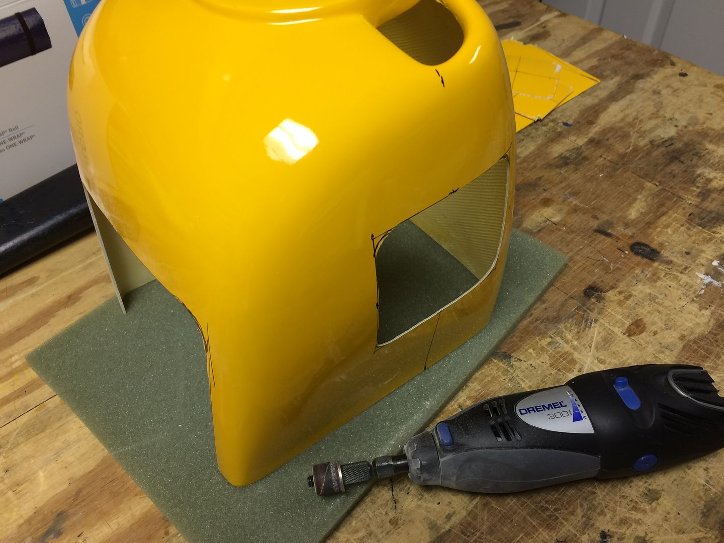
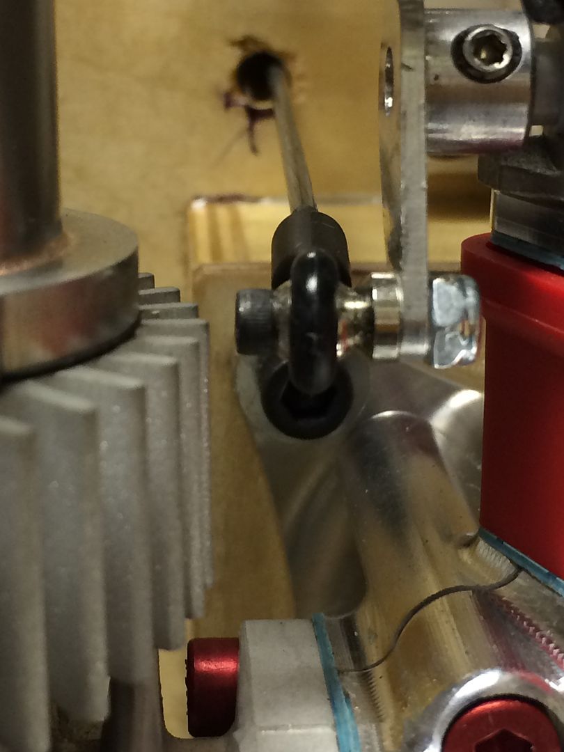
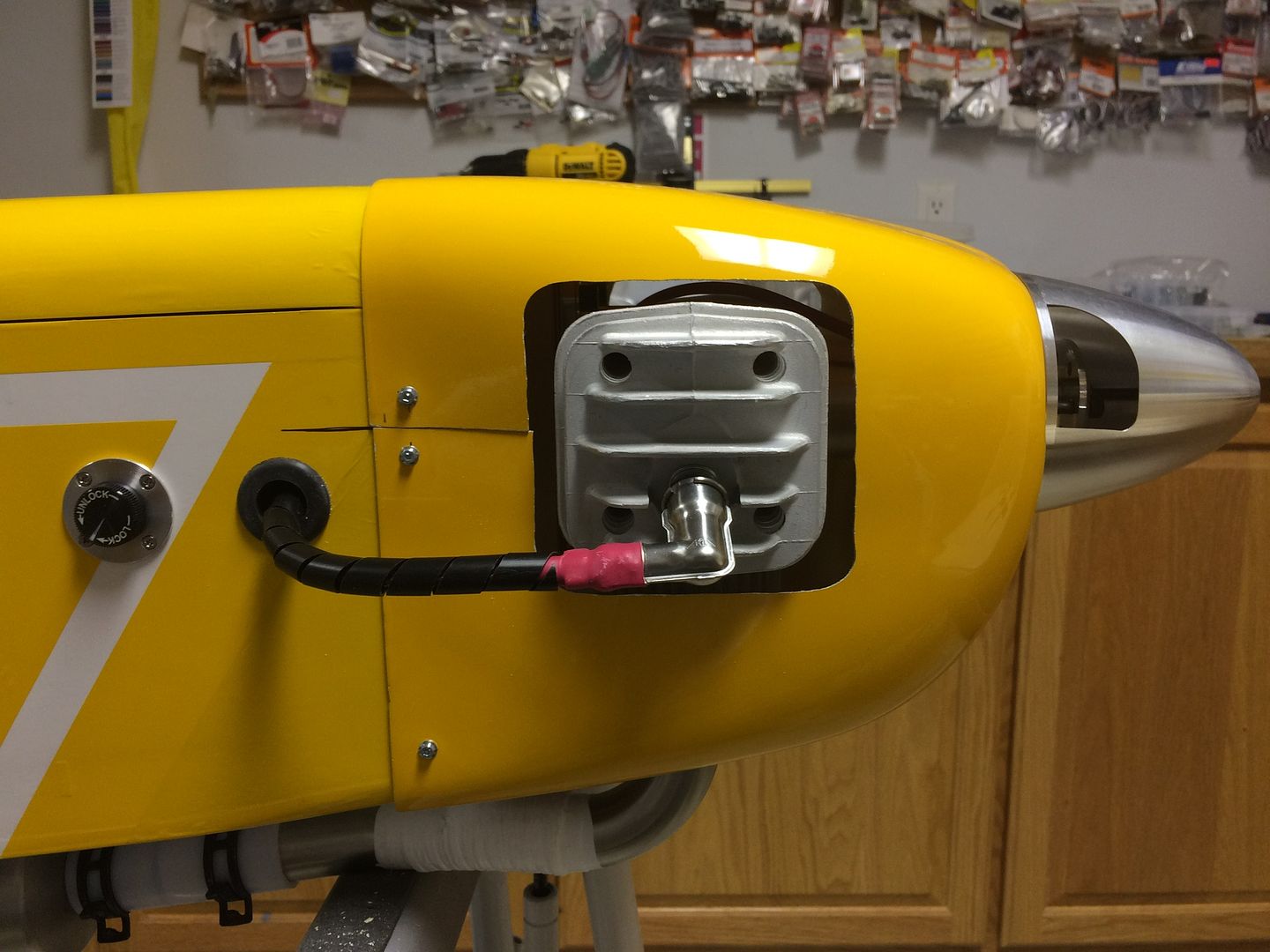
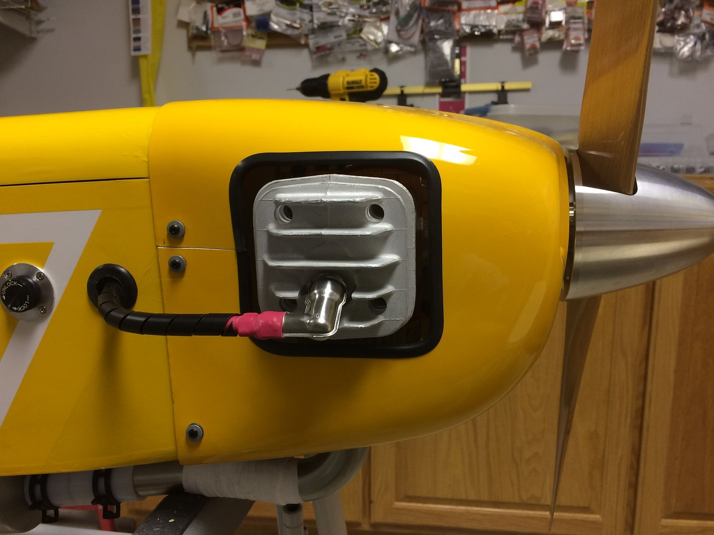
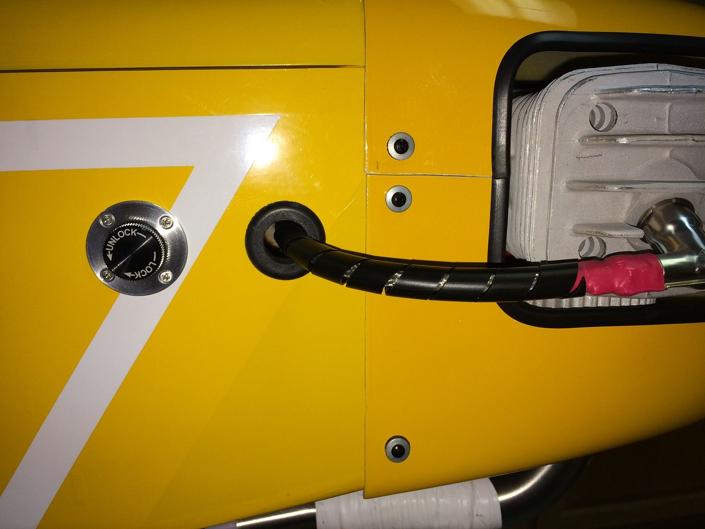
And we also cut out the bottom of the cowling to allow it to fit over the header pipes. Note the black rubber grommet inserted in the cowling (to the left in the picture). This is an access hole to reach the carburetor adjustment screws.
 A Site for Soar Eyes
Comment
-
Jim, you and Len are top notch in building tugs that are super clean in installation and top in reliability. Famtastic examples to follow. The header spacers/extensions are great. Do you know if the cooling find could have been cut 90 degrees to the orientation they are at? Air flow wise they would be happier, but certainly not a point to worry about. Awesome job as a whole and looking forward to seeing it in the air, preferably with one of my sailplanes behind it!!Comment
-
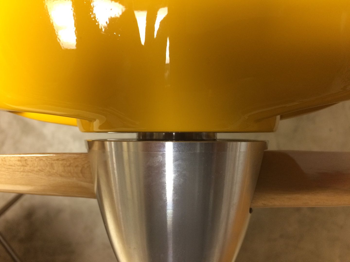
Now that the cut outs have been adjusted for size and fit, the cowling needs to be attached to the fuselage. In order to get the spacing and centering for the spinner, 1/8" plywood spacers were clamped between the spinner back plate and the cowling.
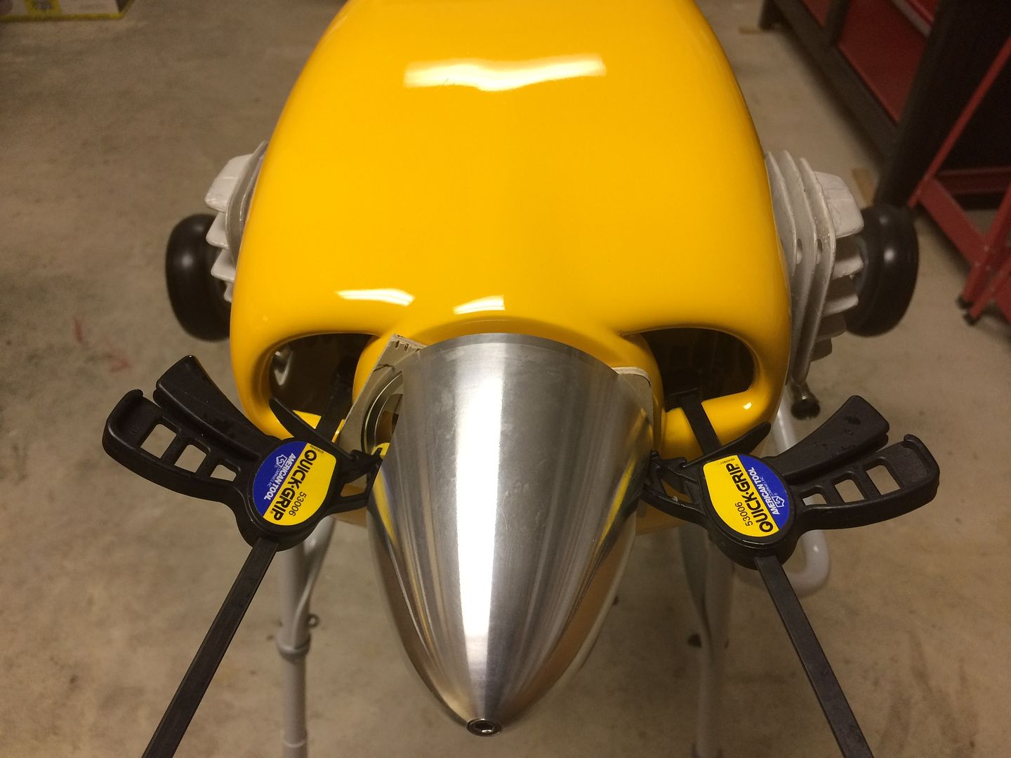
Once satisfied, holes for mounting screws were drilled and screws installed.
Spacers and clamps were removed and the centering and spacing was rechecked.
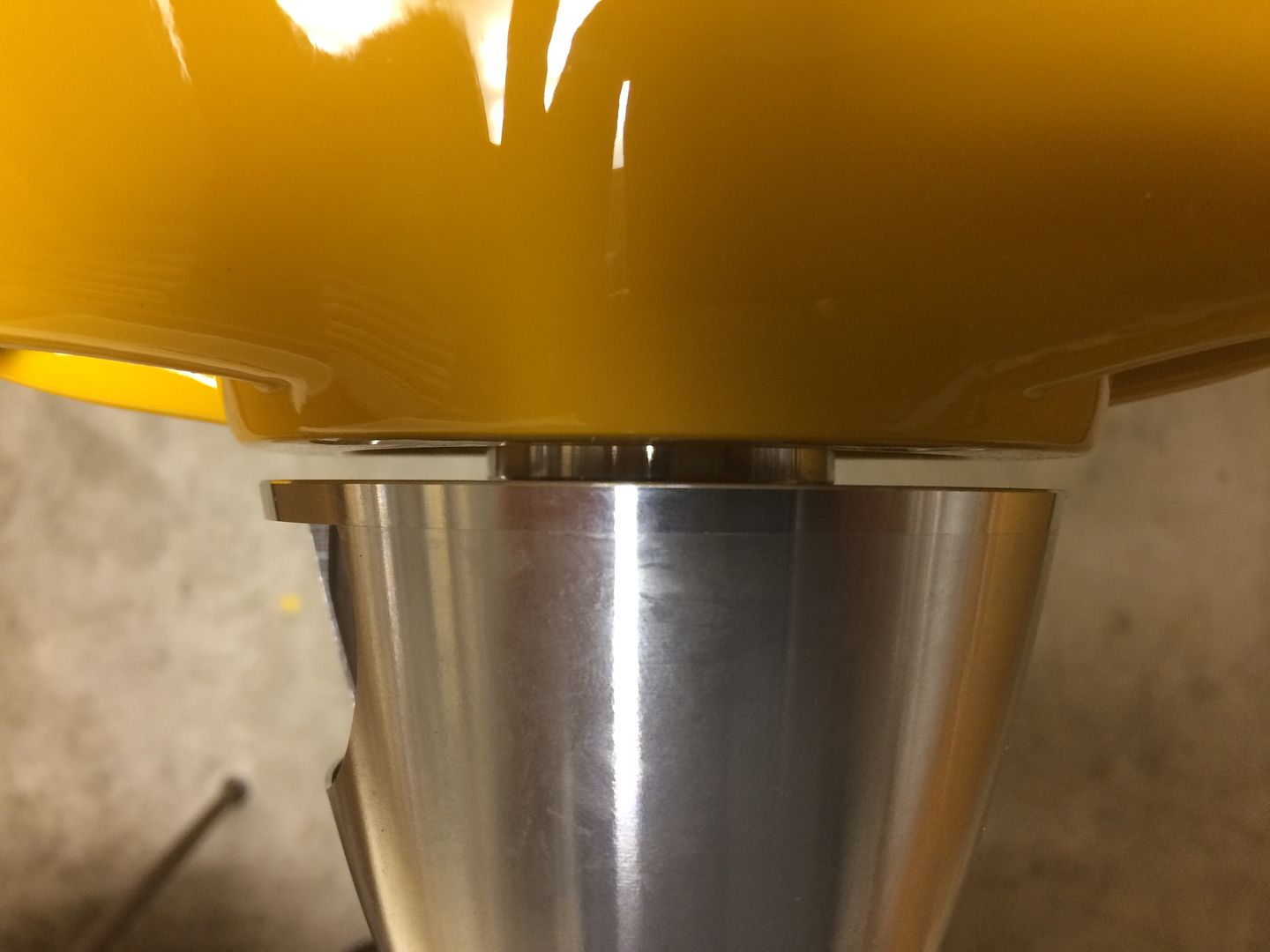
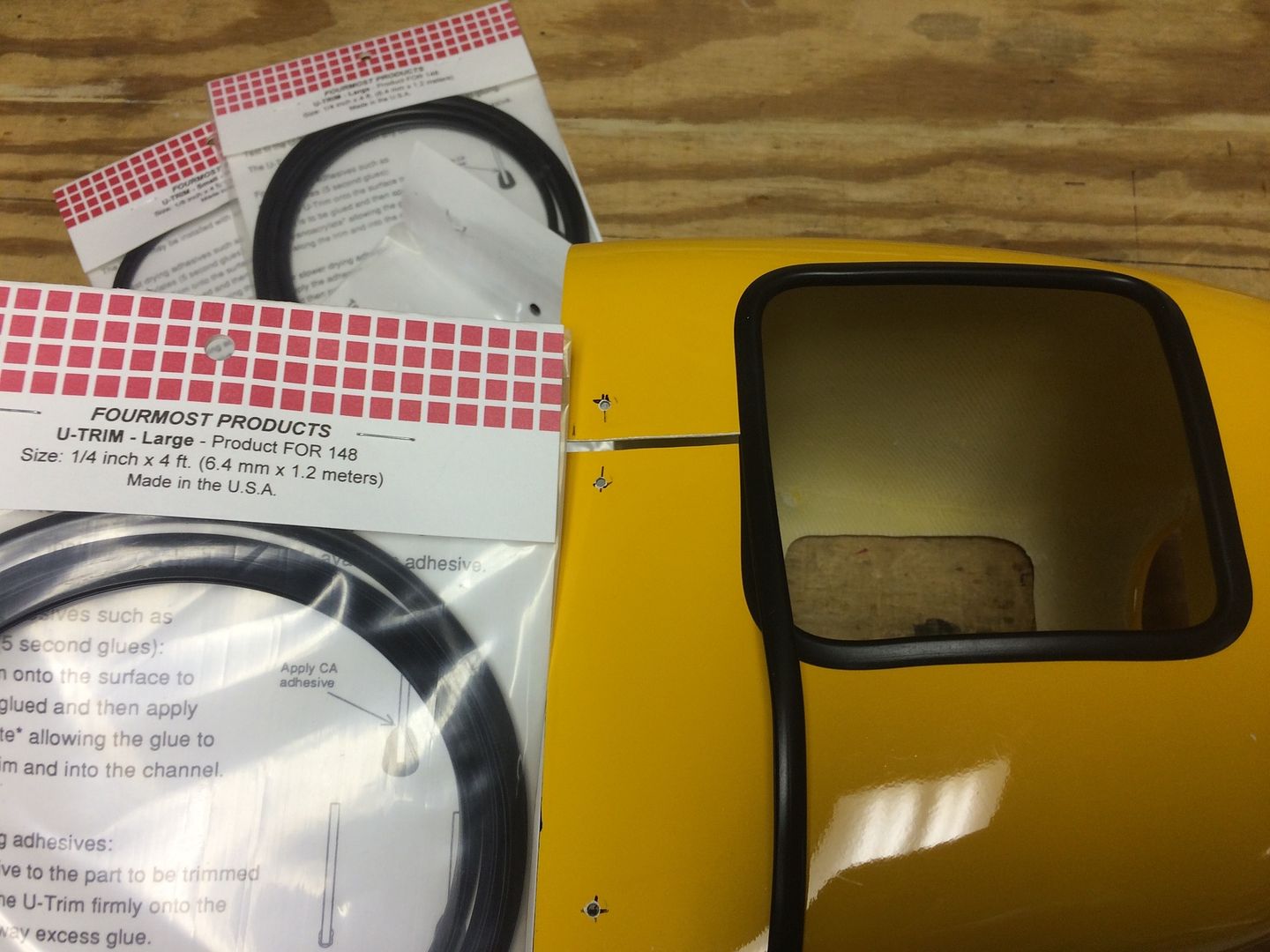
A nice finishing touch is to cover the raw edge of the fiberglass with Foremost 1/4" U-trim. Wick thin CA around the inside to hold it in place.
Cowling was reinstalled using screws with bonded washers. We have used this method with excellent results over time. The bonded washers help hold the screws tight, resist vibration and chaffing of the holes in the cowling.
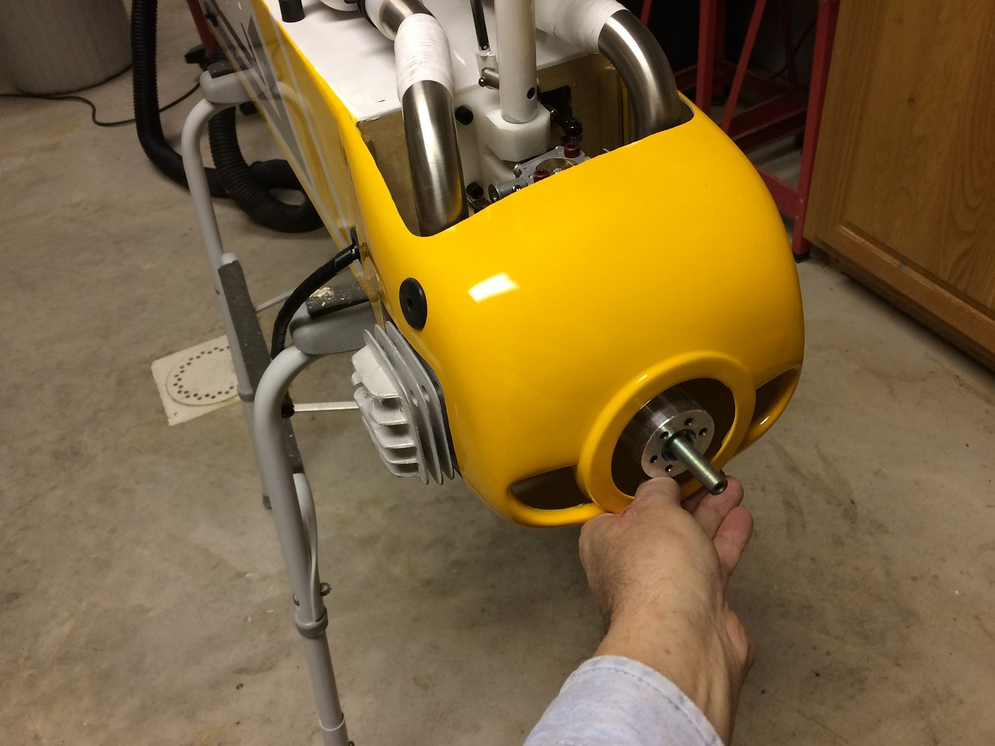
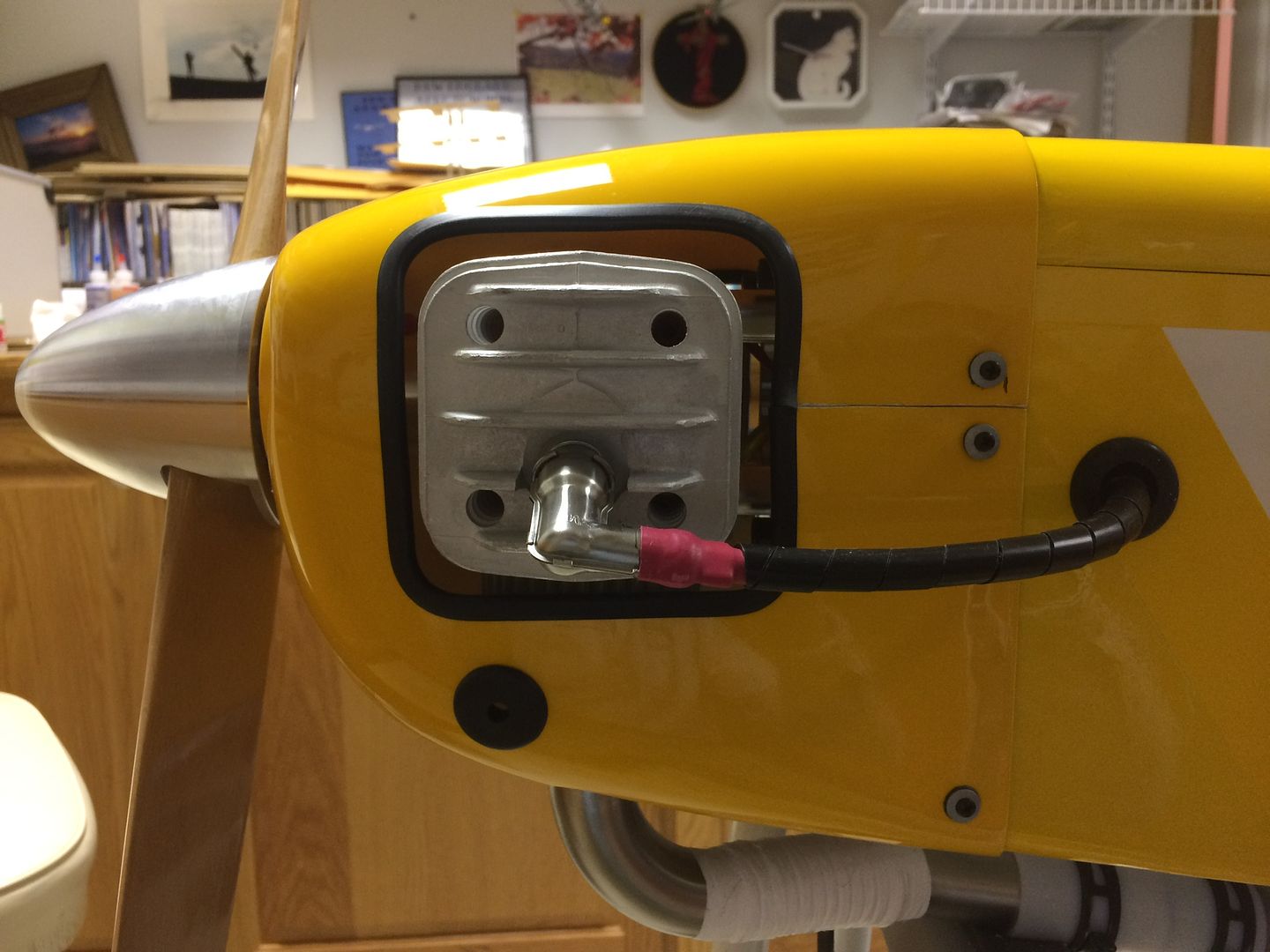
And the other side...and you can see my access for the carburetor screws.
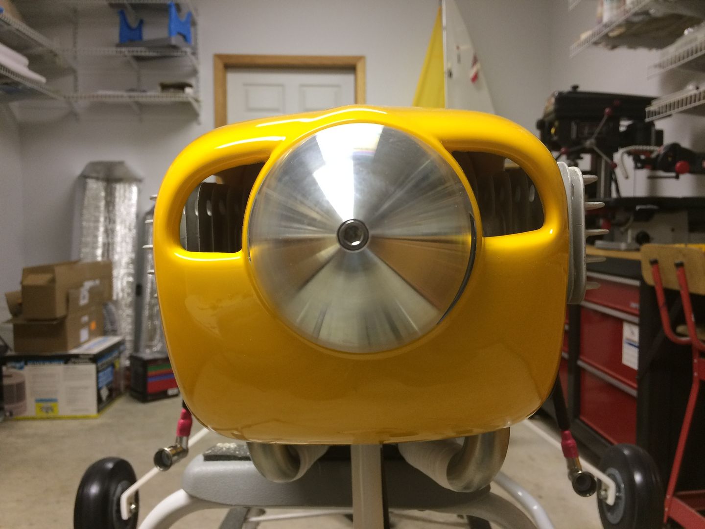
And let's check that centering and spacing with a prop installed.
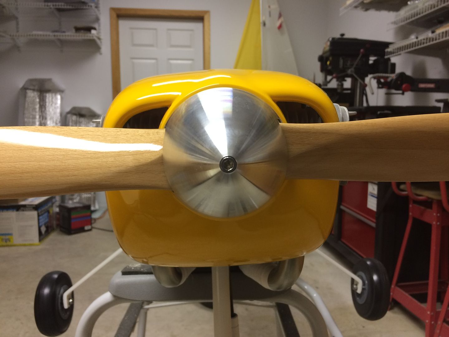
Looks good!
A Site for Soar EyesComment
-
REALLY NICE JIM..
Congrats on the build. Great info and well documented, thanks for taking the time to do it.
LenLen Buffinton
Team Horizon HobbyComment
-
a great way to end 2016! congrats on another fine build. Look forward to seeing her in the air.
MattComment
-
Thanks guys, Happy New Year!!!
The Bidule 111 v2.0 is ready to party like its 2017!
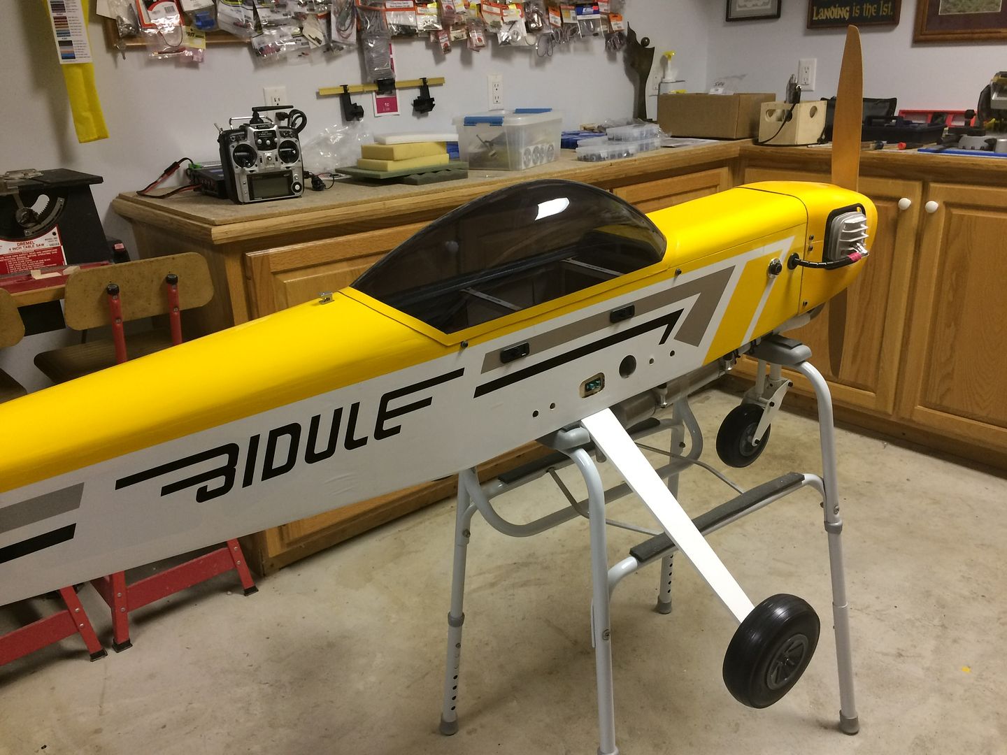 A Site for Soar Eyes
Comment
-
Looks very nice Jim! But, I think that something is missing, and I don't mean the wings.
Happy New Year!!
Steve KSteve K
Kremer Aerotowing TeamComment
-
I am looking at the Bidule 170, and the graphics do look a little different.
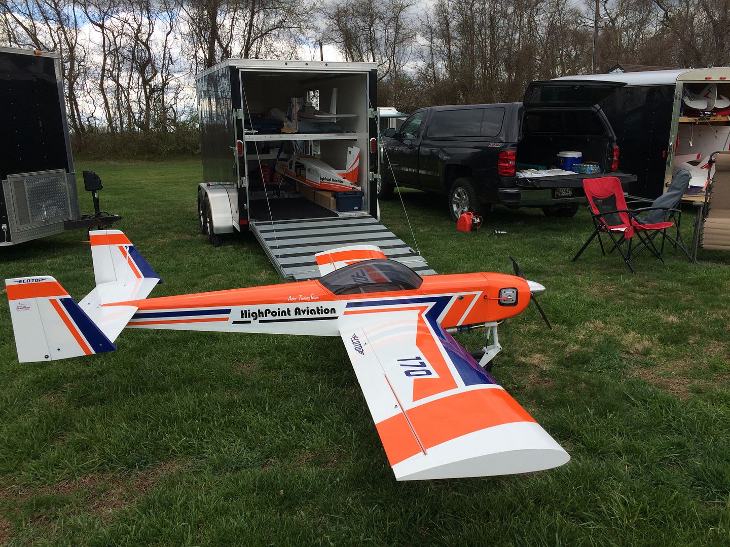 A Site for Soar Eyes
Comment
-
That is what I was referring to
Steve KSteve K
Kremer Aerotowing TeamComment
-
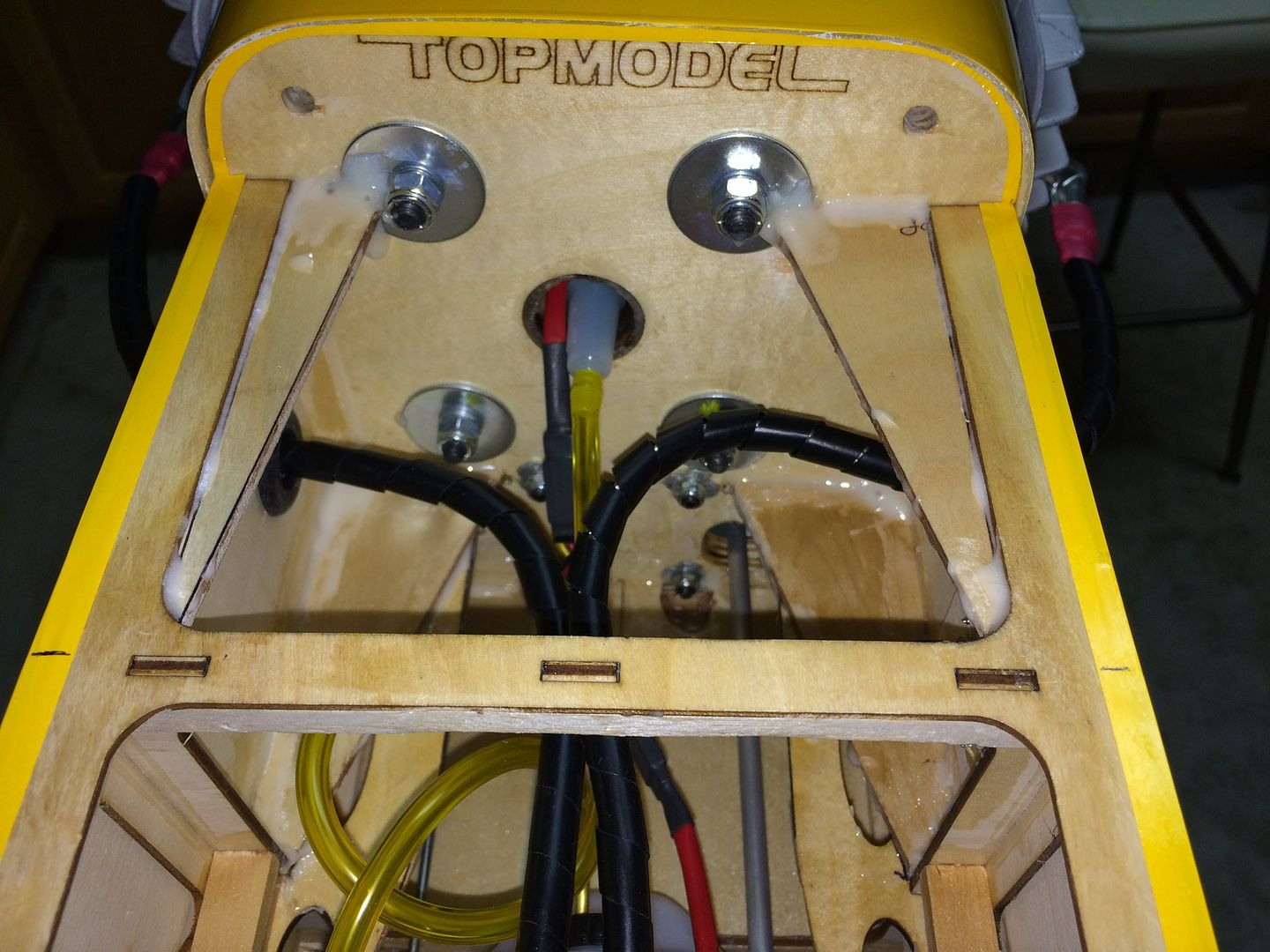
Time to finish out this build project. Thought it would be a good idea to go from front to back in the fuselage and show where and how we located everything.
Starting with the firewall, the fuel line (with inline fuel filter) and ignition wire run out through the center tube and into the engine compartment. The ignition wires exit the fuselage sides and the holes in the fuselage are cushioned with rubber grommets.Three plywood gussets were added down each side of the firewall to tie it to the longerons along the fuselage sides. We cut the cut section out of the stock plywood shelf in the first two fuselage compartment bays.
The fuel filler valve is located on the right side of the fuselage within the first bay.
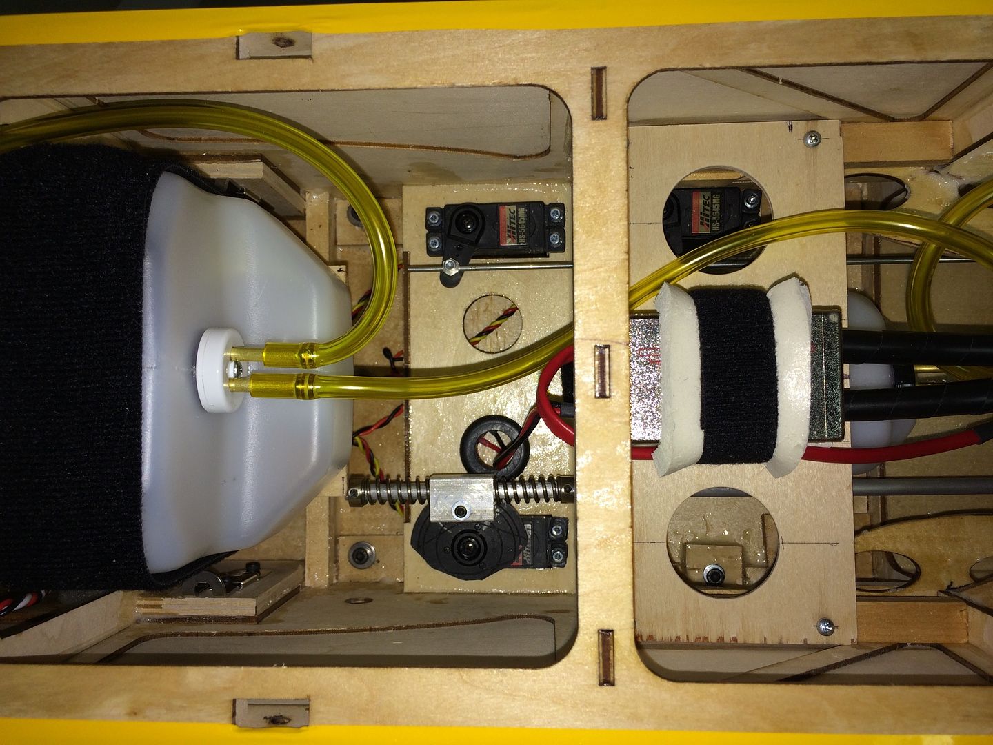
As we go back into the second bay, a 10oz DuBro fuel "header" tank is located on the center floor area, the throttle servo is located on the left fuselage side, and a shelf above holds the ignition module. This shelf can be removed to access the fuel tank and throttle servo. The steering pushrod runs along the right side of the header tank.
As we go back into the third bay, the stock servo tray was used to hold the steering servo on the right side and the choke servo on the left. The front support for the main 50 once fuel tank is behind these servos and the slide latches for the wing attachment are to either side of the main tank.
The 50oz DuBro main fuel tank is held to its mounting shelf with Velcro straps front and back. The fuel tank shelf bridges over the tube for the wing-tube pass through and the ignition battery is located under this shelf behind the tube. The switch for the ignition battery is located on the right side of the fuselage beside the main tank and near the ignition battery.
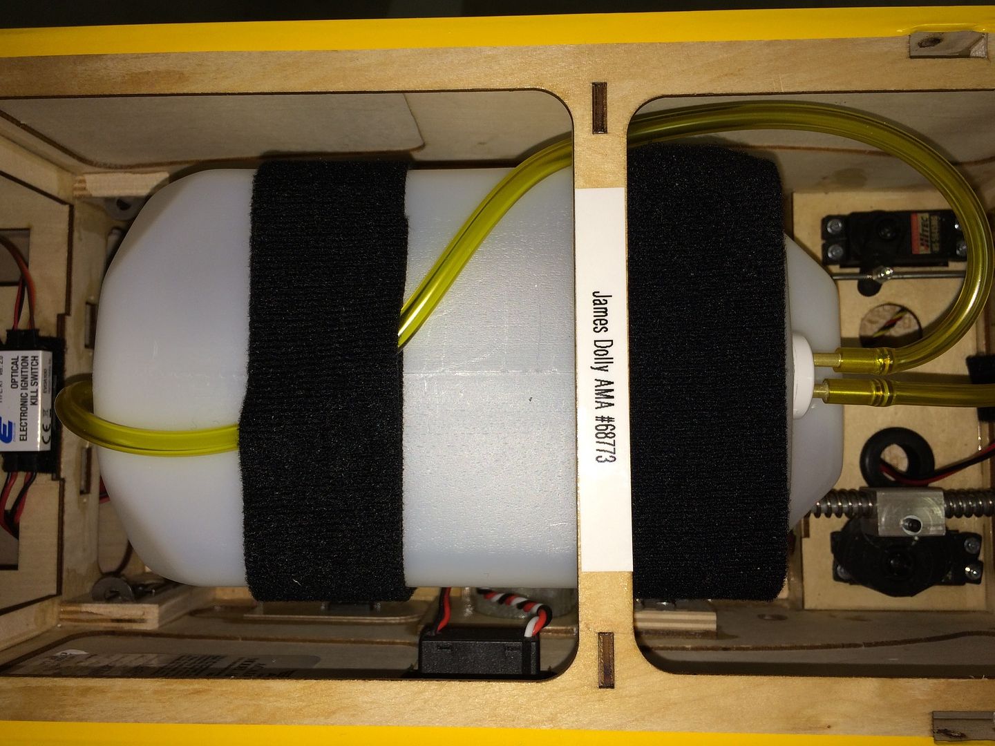
The main fuel tank is centered over the CG so fuel depletion does not affect the CG. It also just fits under the cross-member between the third and fourth fuselage bays.
A Site for Soar EyesComment
-
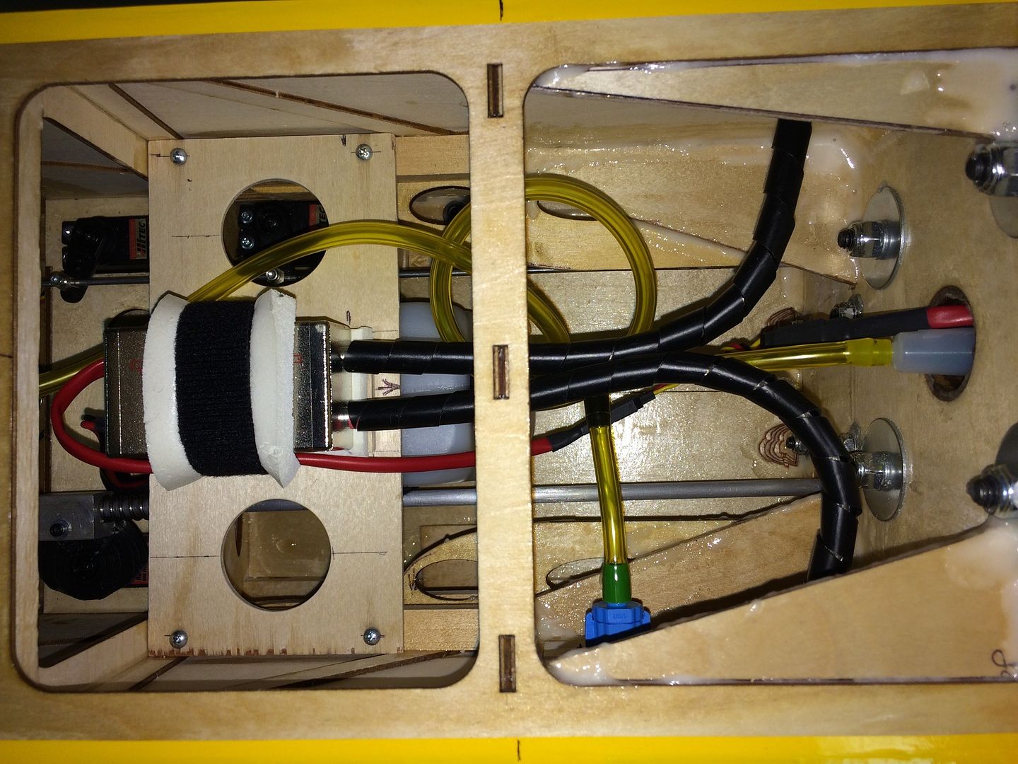
The slide latches for the rear wing attachments are behind the main tank and the vent line fuel fitting goes out through the floor in this bay.
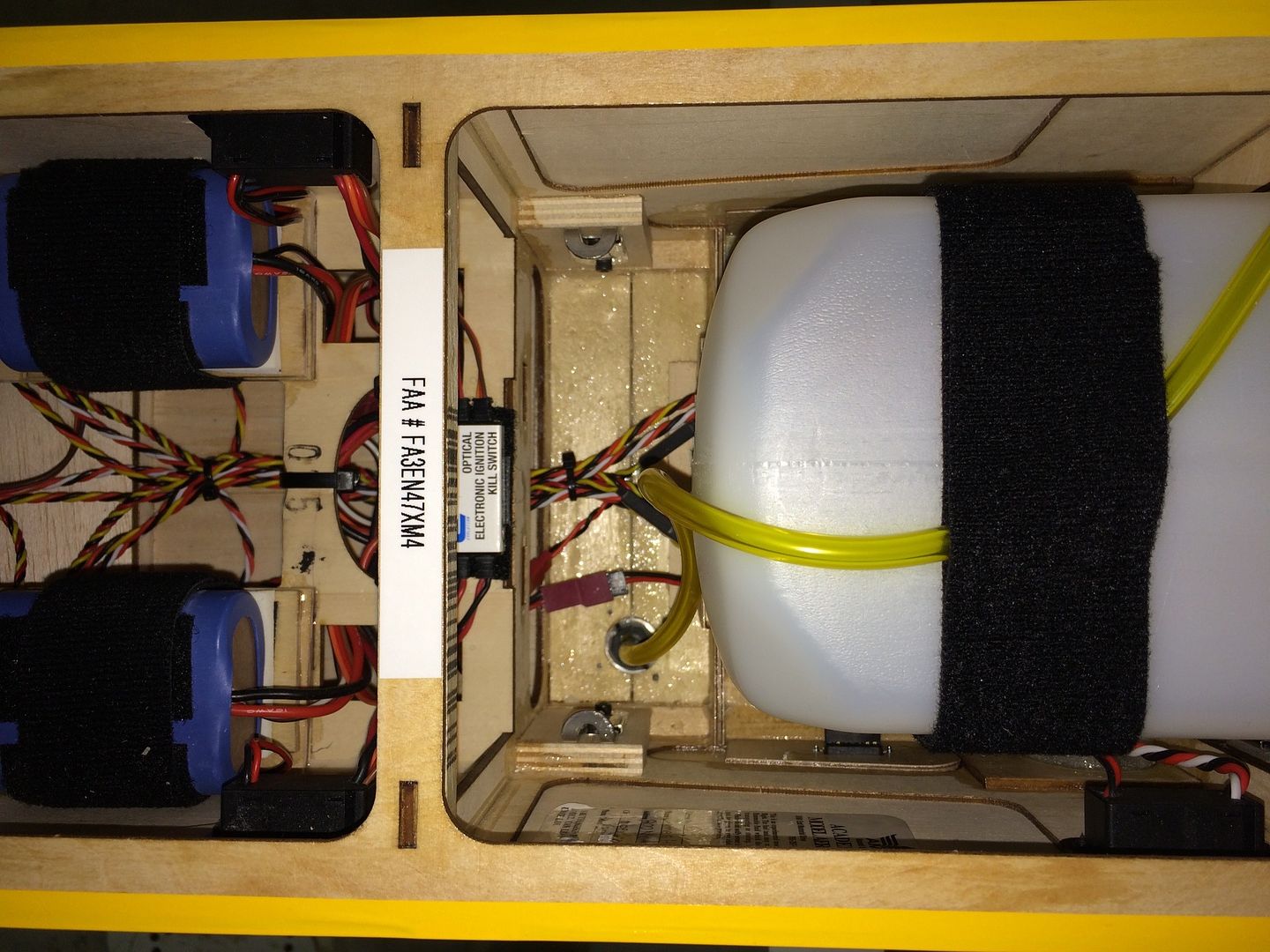
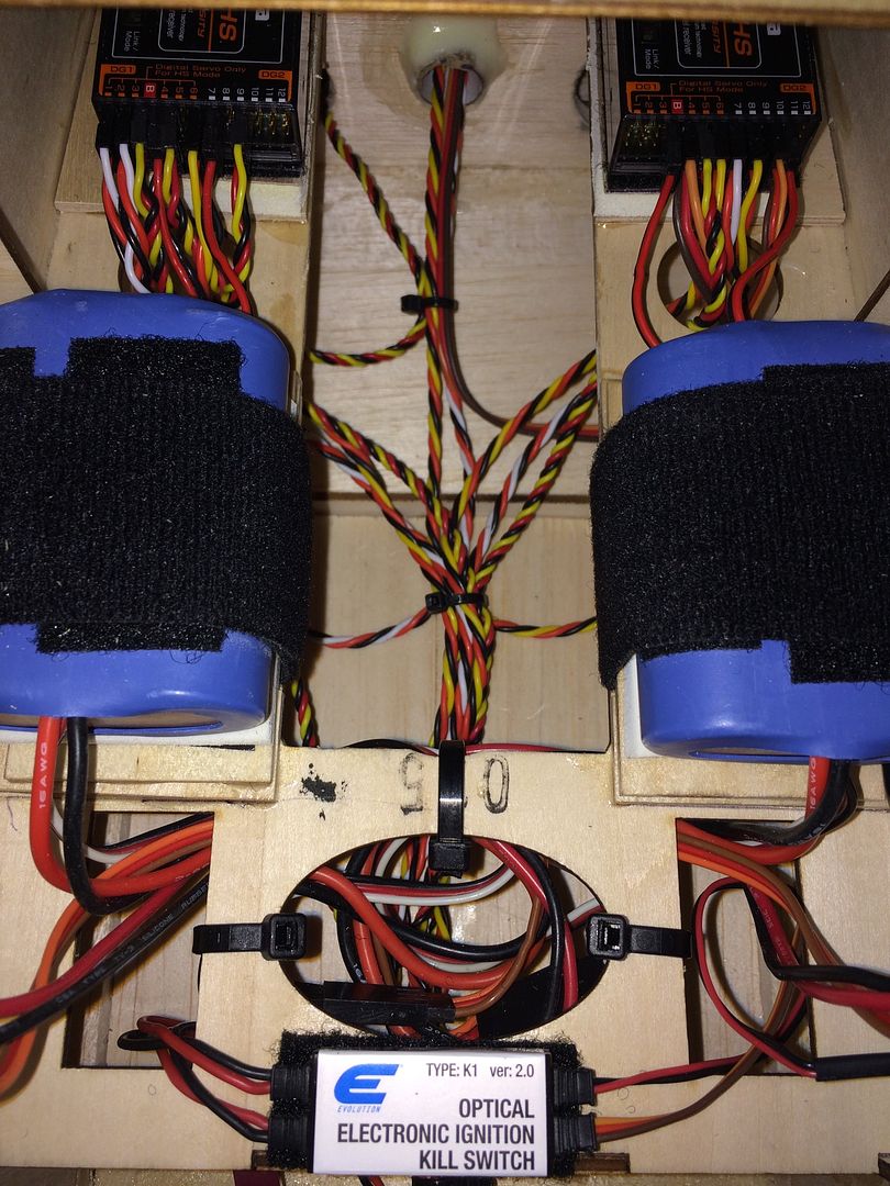
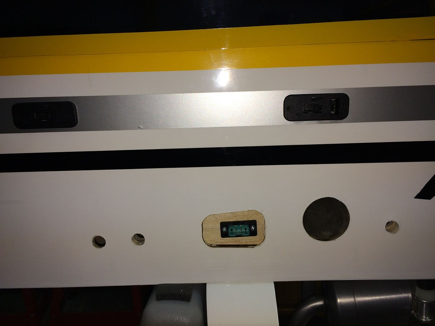
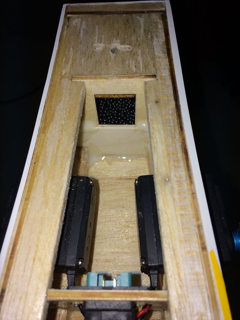
There is a shelf in the last two bays and, like the one in the front, we cut the center section out to gain access below. The cardboard tube that routes the servo wires forward from the tail opens into this area. Once again, we are using the dual receiver/battery/switch setup in this plane. This divides the servo load between the two receivers and provides redundancy. The batteries are mounted with Velcro for ease of removal and both receivers and batteries are mounted on foam pads for vibration damping. The ignition kill is mounted on the cross bar with Velcro. The switch for each battery/receiver combo is located on the fuselage side. These switches are ED Ultra Switches with built in charge ports.
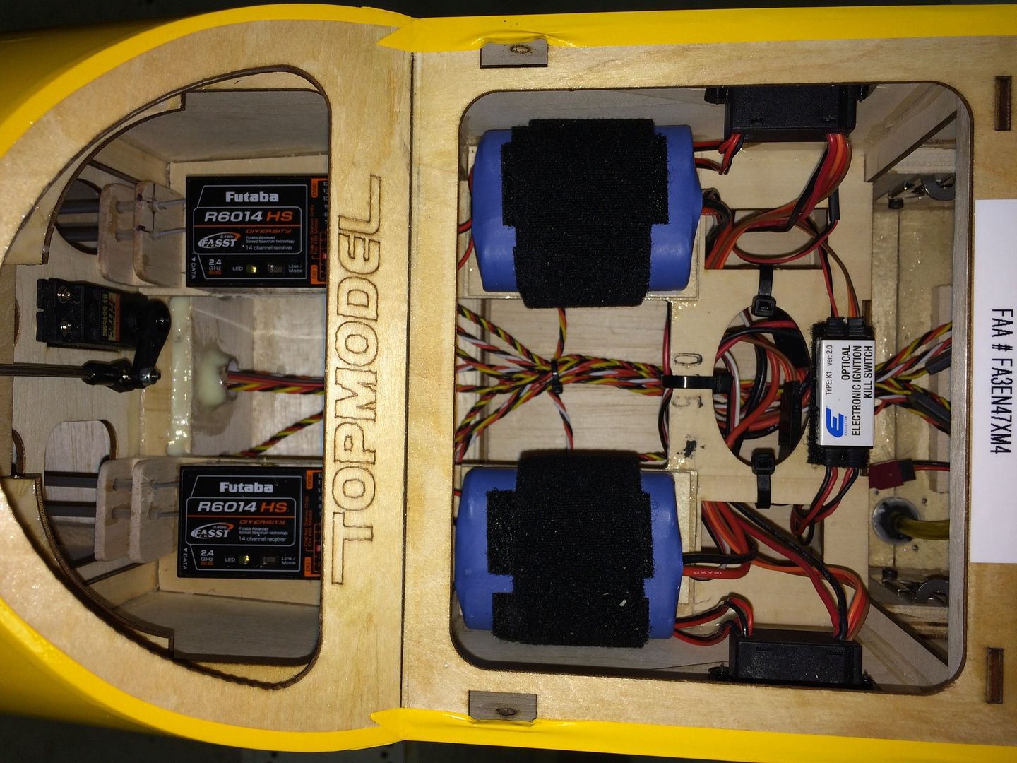
Each switch has two power leads that plug into the receiver at two different locations to spread the power delivery across the bus board.
Multiplex connectors for aileron and flap servo connections are located in the fuselage side.
Final step was balancing. Our model required 9oz in the tail to balance. A mix of epoxy and lead shot was poured into the last section of the fuselage under the stab mount.
We plan to use a Xoar 26x10 wood prop for break-in and then switch to a Mejzlik 26x10evo carbon prop. Now waiting for the weather to provide a good test flight opportunity!A Site for Soar EyesComment
-
Exceptional job Jim.
The setup is clean and efficient as always. Adding 9oz to the tail is pretty minimal considering all the stuff up under the cowl, motor, canisters, headers, etc. Great job keeping the equipment to the rear.
Looking forward to seeing it fly soon
Len Buffinton
Team Horizon HobbyComment

Comment