Announcement

Collapse
No announcement yet.

Bidule 111 v2.0

Collapse
X
 
  • Filter
  • Time
  • Show
Clear All
new posts

  • #16
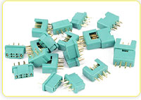
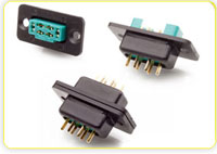
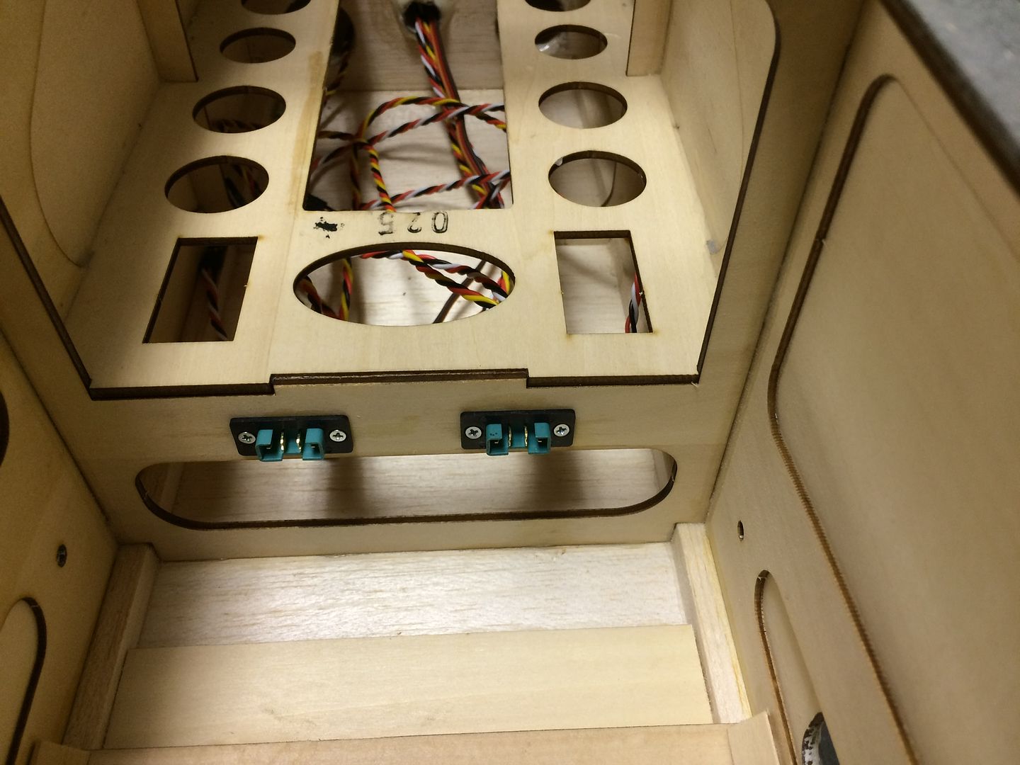
    Cool stuff James! I have never seen those "solder boards" for the MPX connectors!! What is there purpose? Are they easier to solder than trying to solder the wires right on the lugs? I like how the edge of the board has knurls, that gives the heat shrink something to hold onto. I have soldered to the lugs before then used heat shrink, but if I'm not careful when unplugging them, I pull the heat shrink off. To remedy that I thought about buying one of those molds for MPX connectors. There are a couple versions out there...I'm sure you may have seen them. http://plugmolds.com/plug-molds/1/multiplex-plug-mold but the molds aren't cheap. How much are those boards and who has them?
    Pete

    Comment


  • #17
    If you look back Pete you will see the links to Esprit in the thread. cool stuff.
    Len Buffinton
    Team Horizon Hobby

    Comment


    • Xroadie
      Xroadie commented
      Editing a comment
      Thanks Len....I missed the link

    • JimD
      JimD commented
      Editing a comment
      I was busy posting this morning and the forum went offline for a few minutes and caused a hiccup! Didn't save everything, so I will go back and fix things.

  • #18
    With the cardboard tube and mounting plates in place, the rudder wiring harness was installed using the slot built into the fuselage frame by TopModel. (nice touch, this is also the same on the Bidule 170)


    Forward end of cardboard tube.


    Next, we add the elevator servos. The openings were prepared by cutting the covering in an X pattern and then using a trim seal tool to adhere the covering to the sides of the servo openings.


    Using our "dead servo" as a drill guide, mounting holes were drilled and hardened with thin CA.


    Here is a neat trick for installing the brass eyelets in the rubber bushings. Stack the eyelets on a ball driver (2mm size here) and then push them up through the rubber bushings...quick, simple, and painless process!


    A pair of 32" extensions were fabricated using twisted W/R/B wire for the right servo and twisted Y/R/B wire for the left servo. This makes it easy to tell which is the right elevator and which is the left elevator lead when plugging them into the receiver. As seen in the photo above showing the rudder extension, the rudder extension was fabricated using flat Y/R/B wire. Again, it is easy to tell which lead coming from the tail servos goes into which receiver port. Here are the wires coming out of the front side of the cardboard tube.


    Last edited by JimD; 11-23-2016, 03:16 PM. Reason: Added pictures
    A Site for Soar Eyes

    Comment


    • #19
      So, remember the extensions we made for the wings.


      Now is the time to install the fuselage part of those extensions.We used a small drill in a pin vice to drill starter holes for the mounting screws. Those holes were then reinforced with thin CA.


      Then the right and left wiring harness parts were installed. Again, these slots are built into the model by the manufacturer and the MPX connectors in the mounting housings fit perfectly! Very nice touch by the TopModel designers. Thanks guys!!!!


      A Site for Soar Eyes

      Comment


      • #20
        While we are inside the fuselage, lets go ahead and install the tow release mechanism (which is included in the kit) and servo.The mounting holes and 3mm blind nuts are built into the fuselage. Phillips head bolts and plate washers are supplied, but personal preference, we used socket head bolts and lock washers along with Blue Thread Locker for mounting the tow release mechanism.


        We had to trim a piece of a stringer out of the aft side of the opening on top of the fuselage in order to get the mechanism to mount flat against the bulkhead.


        The servo was connected to the control release rod using a DuBro 4-40 Heavy Duty Ball Link. By mounting this ball link on the underside of the arm, we got a nice straight alignment of the control rod.

        A Site for Soar Eyes

        Comment


        • #21
          At first glance, the Bidule 111 main gear looks to be symmetrical, but it is not...it has a slight sweep one direction. This is the same on the Bidule 170. We elected to mount the main gear on our Bidule 170 with the gear sweeping forward and will do the same on this model.

          Note the reference line on the surface of the workbench and the triangle relative to the gear leg.


          Here is the gear turned 180 degrees.

          A Site for Soar Eyes

          Comment


          • #22
            This spawns a thought here Jim. My Bidule, though it is a 170, is pretty "light" on the nose gear and I wonder if flipping the gear around would make much of a difference. The axle seems to shift aft a decent amount. I don't find the 170 set-up any problem at all, but it just spawned the thought. Thanks for the great build thread, always a joy to follow and read.

            Scot

            Comment


            • JimD
              JimD commented
              Editing a comment
              The mounting holes in the gear are symmetrical, so the gear can be mounted either way no problem.

              Interestingly, my Bidule 170 has the gear racked forward and does not seem to be prone to sitting tail down like yours and Len's...and this is in spite of having a lighter weight engine in the nose of mine. Also, I am not nose heavy in that I can drag in nose high for landings without any problems.

          • #23
            The Bidule 111 kit does not include wheels (the Bidule 170 does, but, by personal preference, I changed those out for DuBro Treaded Lightweight Wheels).

            Since the DuBro Treaded Lightweight Wheels were so successful on my Bidule 170, decided to use the same type wheels on the Bidule 111. We will be using 6" wheels on the mains and a 5" wheel on the nose. The 6" wheel has a 3/16" (5mm) axle hole, but can be drilled out for a larger axle if needed.


            The plan was to use DuBro 1/4" axles, but some measurements may have changed my mind. First of all, the composite gear is fairly thick, 8.25mm.


            And the axle hole in the gear is 7.90mm


            The diameter of the threaded mounting section of the stock axle is 7.65mm and is a loose fit in the 7.90mm hole. This can be fixed by putting a small amount of JB Weld or thickened epoxy around the threads when the axles are installed into the holes of the composite gear.


            The length of the threaded section on the stock axle is 17.00mm and the width of the stop nut is 6.43mm. Adding things up. the gear is 8.25mm thick and the stop nut is 6.43mm thick equaling 14.68mm of total thickness. This leaves 2.32mm of extra threads on the 17.00mm threaded section after the stop nut is tightened down. This also allows for a plate washer to be added between the gear and the stop nut.


            By comparison, the 1/4" DuBro axles have a larger diameter threaded mounting section (11.20mm) which means the 7.90mm hole in the gear would need to be significantly enlarged for the DuBro axle to fit.


            The length of the threaded section on the DuBro 1/4" axle is 14.20mm and the width of the stop nut is 7.98mm. Adding things up, the gear is 8.25mm thick and the stop nut is 7.98mm thick equaling 16.23mm of total thickness. This means the threaded section of the axle is 2.03mm short of having enough threads to secure the stop nut.


            As for the stock axle supplied in the kit, its diameter is 4.96mm or just under the 3/16" (5mm) diameter in the DuBro wheel. Looks like the wheels that we selected will bolt on directly with no need for modification.


            Last edited by JimD; 11-23-2016, 07:13 PM.
            A Site for Soar Eyes

            Comment


            • #24
              Since we decided to use the stock axles and since the holes in the landing gear offer a loose fit, we decided to use some West Systems Epoxy and #404 Microfibers to fill this void and create a snug fit. Just in case the axles do need to be replaced, we did not want the epoxy to bond too tightly to the metal axles.So, the metal parts were painted with Vaseline before coating them with the epoxy mixture. One little trick we like to use when painting on something like epoxy or Vaseline is to cut the bristles of a flux brush at an angle. Makes the application process more controllable.


              A plate washer was added to the axle between the lock nut and composite gear. You can see that some of the epoxy mixture squeezed out around this washer.


              While we had the epoxy mixture ready to go, we used some to install the dowel pins into the leading edge of the stabilizer. The supplied carbon rod dowel pins were only one inch long. Inserting a small rod into the holes, we discovered that they are 3" deep. We elected to use 1/4" wood dowel rods 3-1/2" long and epoxied them in with the West Systems epoxy mixture.

              The axle hole in the 6" DuBro wheels was enlarged slightly by running a 13/64" drill bit through them. This created a nice fit on the stock axles with no wobble.

              Last edited by JimD; 11-23-2016, 11:48 PM.
              A Site for Soar Eyes

              Comment


              • #25
                We interrupt this Bidule build to show the status of Porter #5. Got the cowl trimmed and installed. Thanks Jim.

                Steve K
                Steve K

                Kremer Aerotowing Team

                Comment


                • JimD
                  JimD commented
                  Editing a comment
                  Hi Steve, I am going to have a cowling to cut and fit around the DA-100 for the Bidule very soon. Looks like you did a really nice job! The first one is always stressful..The first time I pushed an X-Acto razor saw through a nice new pristine cowling, doubt was running wild in my mind. Things worked out and the next one was not nearly as stressful...and now Steve K is on his way! Nice work Steve!
                  Last edited by JimD; 11-25-2016, 09:33 PM. Reason: Condensed post

              • #26
                Now that the axles are installed it is time to mount the DuBro 6" Treaded Lightweight Wheels.We like to use a Dremel tool with a cutoff wheel to make a slot in the axle for the wheel collar set screw to recess down into.


                We also added a plate washer to both sides of the wheels before installing the wheel collars. As a final touch, we like to add a short piece of rubber tubing on the stub of axle that extends out beyond the wheel collar.

                A Site for Soar Eyes

                Comment


                • #27
                  In the instruction manual, TopModel suggests the use of 38mm aluminum standoffs in order to get the proper spacing between the engine and the firewall. Our personal preference is to build a plywood box for use as the spacer.

                  The box we built for the Bidule 111 is similar to that used on our Bidule 170 except just proportionally smaller. The sides are 1/4" think aircraft plywood and the inset firewall is 3/8" thick aircraft plywood. Dimensions are shown in the photo of the parts below.


                  We use a TopFlite "Woodpecker" to make little indents in all surfaces to be joined to create epoxy "nails" that make the join even stronger. The parts were clamped until the epoxy and #403 filler mixture cured. Then a 1/8" thick piece of aircraft plywood was added to the front of the box. The final assembly is 1-1/2" thick (38mm).

                  A Site for Soar Eyes

                  Comment


                  • #28
                    Once the epoxy gets set, carefully mark off the center line vertical and horizontal. Then measure 35mm to either side of the vertical line and 40mm to either side of the horizontal line. This locates the engine mounting holes and these will align with the pre-drilled holes in the Bidule 111 firewall.


                    We step drill these holes, first with a small drill bit, then slightly larger, and then full 1/4', this makes the holes come out nice and crisp. The plan was for the engine mounting bolts to go through the box fairly close on each inside corner.


                    The four holes for engine mounting are pre-drilled at 70mm apart across and 80mm up and down. This is the standard mounting pattern for the DA and DLE engines that fit this model. There is also a 1-1/8" center hole for the ignition wire and fuel tubing to pass through the firewall. A cardboard DuBro pushrod container tube is a perfect fit in this hole.


                    We drilled a matching size hole in the center of our engine mounting box.


                    When this bolts up to the firewall, the cardboard tube further helps to align the box in the correct position on the firewall. Once you are sure about the fit, this box is then epoxied into place on the firewall. This is exactly how I did my Bidule 170 earlier this year. That model now has 60+ hours of flight time and the engine mount has been perfect.

                    A Site for Soar Eyes

                    Comment


                    • #29
                      We added supports to the backside of the firewall on our Bidule 170 and will do likewise on this model. We start by making paper patterns (Scrap cardboard from the DuBro wheels works great) for the floor, mid-line, and top stringers. We have noted the failure of the nose gear mount on the lower section of the firewall on three other Bidule 111 models. The decision to add the floor panels was in part to support the lower section of the firewall that takes most of the impact on a nose gear first landing. All parts were then cut from 1/8" thick aircraft plywood.


                      We used epoxy mixed with West Systems #403 microfibers to glue these parts in place.

                      A Site for Soar Eyes

                      Comment


                      • #30
                        Time to commit the engine box to the firewall. For this step, we are using the engine mounting bolts to hold the box to the firewall while the epoxy cures. Note too that we cut the DuBro cardboard tube and epoxied it in place as well. The nose gear was also temporarily bolted into place to check for control rod and servo position.inside fuselage.

                        A Site for Soar Eyes

                        Comment

                        Working...
                        X