Announcement

Collapse
No announcement yet.

Pike Paradigm

Collapse
X
 
  • Filter
  • Time
  • Show
Clear All
new posts

  • Pike Paradigm

    I've been waiting for a new toy. All the servos, motor, prop, electronics have been sitting in a box for a few months. Things finally made it to NJ by way of CA.

    I assembled all my parts. Model came with wing LDS servos installed. I have to do the rudder and elevator servo install. Motor and prop is on the nose and the battery pack is in there. All the parts are currently around 4600g and CG close to 104 where I'll start. MKS6625 installed in the wing. Lots of power since these are some pretty large surfaces. The plane barely squeezed onto my CG scale so I could check how close I would be to the CG range. It is good.
    Click image for larger version

Name:	Paradigm Initial CG (1) (Large).jpg
Views:	661
Size:	40.4 KB
ID:	48873

    The wing tip LE's needed a little sanding. Better under sanded than over sanded. Tip panels are still a pain to get on I think they changed the tip angle from what was originally put into the wing tips. The mold angle appears around 6 degrees but the joiner is around 8 degrees. So the pins don't slide in as nicely as they could.

    I have to get used to the really big vertical fin That is the one unusual bit.

    Wing center, 1616g (Servos installed)
    Left tip 454g (Servo installed)
    Right tip 450g (Servo installed)
    Nose 280g. It is a lot of fiberglass. About 1.5mm thick.
    Stab 52g
    Fin 90g , It is really big
    Boom/wing mount 4726
    Joiners 126g
    Misc cables, screws 84g

    Ballast is up to 8 bars that add up to 2300g

    So with full ballast, it should be close to 7000g

    Click image for larger version

Name:	Paradigm Initial CG (2) (Large).jpg
Views:	659
Size:	27.7 KB
ID:	48872

  • #2
    Very nice. Thanks for posting with all the details. This seems to be “the” sport class of choice. Enjoy and keep us posted.
    Team PowerBox Systems Americas... If flying were the language of men, soaring would be its poetry.

    Comment


    • #3
      First step on the nose, drill the front end for the motor. I made a template on the CNC router for the bolt hole pattern and the outline of the front housing. Drilled the four holes and scribed the line for the front end. Then used a dremel to open up the front for the motor. Leomotion 3631-2050 with a gearbox. Up to 1900 watts (15 seconds) so it should be able to handle things. It's a little more powerful motor than the 4023 that is on the Samba web page. This thing is going to be flying at 7kg.

      Click image for larger version

Name:	Motor Mount (2) (Large).jpg
Views:	583
Size:	80.6 KB
ID:	48881

      There is a tray provided for the front end. I sanded the edge a little to lower the tray slightly. My 6S2700 pack should fit anywhere I want up front. The YGE-95LVT ESC sits right under things.

      I will need to run a bunch of wires from the front back to the RX. Throttle/BEC Power, Telemetry cable, servo channel for Sparrow. I'm also going to try and add a remote RX up front. The nose is all glass. Even that black colored stuff on the side is supposedly glass. Only a small amount of boom carbon extends at the very back edge where the nose slides in. Hopefully I don't have to remove the nose very often.

      Click image for larger version

Name:	Motor Mount (1) (Large).jpg
Views:	592
Size:	39.2 KB
ID:	48880

      Comment


      • #4
        I’m going to look at the new Nan Compass in a few days, I’ll be curious to see a Paradigm up close as well. They both look very nice. I like this size of model beyond just GPS competition.

        Comment


        • mlachow
          mlachow commented
          Editing a comment
          There should be several of them in California. There were three others in this batch to Flightcomp. Hopefully mine is ready to go by the end of the month and I can find a nice day to fly it.

      • #5
        What’s the wing span?
        TEAM GORGEOUS

        Comment


        • #6
          Click image for larger version

Name:	
Views:	0
Size:	14.3 KB
ID:	48886

          The version that began mass production four months ago has gained great popularity for its excellent flight characteristics. A big advantage is the possibility of landing in higher grass and on unimproved terrain compared to the X-tail.The connection of pushrods to the vtail control surfaces is made using massive ball
          Team PowerBox Systems Americas... If flying were the language of men, soaring would be its poetry.

          Comment


          • mlachow
            mlachow commented
            Editing a comment
            The pages have a good description of the design process.

        • #7
          Some simple stuff. The battery tray gets glued into the nose with some West Systems G/Flex. I also added connectors to the YGE controller that will sit under the battery tray. I have a 6S2700 pack which should be good for two climbs and course time and some spare change. I also marked up the boom part for cutting holes for the MKS HV737 and 747 servos. 737 is the faster one for the elevator. 747 will be for the massive rudder with the short control horn.

          Click image for larger version

Name:	Glue Tray (Large).jpg
Views:	549
Size:	88.3 KB
ID:	48888

          Comment


          • #8
            Can you measure the distance from the trailing edge to the front of the vertical fin?

            Comment


            • mlachow
              mlachow commented
              Editing a comment
              115cm from te to le of fin

          • #9
            Other measurements.

            Tip panel 1552mm
            Center panel 1838mm
            Fin 515mm
            Stab 660mm

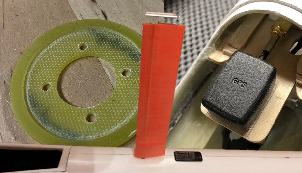
            The fuselage can be taken apart The nose comes off and the fin comes off. They provide a plastic piece to protect the rudder pushrod when you take the fin off.

            Boom with pushrod protector on. 1600mm
            Fuselage with nose on and spinner. 1972mm
            Fully assembled fuselage and fin/rudder. 2056mm

            So you need 2.1M in your car/van/trailer for an assembled fuselage and teh center panel is pretty large too.

            Comment


            • #10
              The rudder and elevator servo are a simple install. Cut a hole in the tray and drill some servo screw holes. Pushrods get trimmed to length and the threaded end gets glued on. The biggest wait is epoxy curing. I do crimp the brass a little for mechanical plus JBWeld. This is a lot easier than working on a 2PK. There is a lot of room to get to the pushrods in comparison.

              The hole for the wing wing wiring also needs to be cut. You just have to cut out the middle enough to feed all the wires through. I relieve the edge of the 6-pin connector a little. Two quick swipes with a plane to put a bevel on it. Then I glue it in place with hot glue. The hot glue has a little flex and adds some strain relief to the wires too.

              Click image for larger version

Name:	Wing wire (Large).jpg
Views:	635
Size:	61.5 KB
ID:	48920

              Click image for larger version

Name:	Servos (Large).jpg
Views:	534
Size:	51.3 KB
ID:	48919


              Comment


              • #11
                I put an 18500 battery pack in under the wing. There is a dual battery zepsus switch in there, one that passes through the ESC and one that connects to the extra battery. I set up the YGE controller to 8.2v so it should always be around there. Alarm is set down 7.8v which should happen a little while after the ESC stops delivering any power. I also have an alarm on the motor battery voltage, but nothing will happen if the YGE just stops working and stops feeding telemetry. The main RX is towards the back of the wing and the antennas exit just behind the wing. A second remote RX is up at the back of the nose cone for some more antennas up there.

                The radio setup data is pretty time consuming to input and check. There are 6 different flight modes. If you look at them, they appear really well done. The dual rates and mixes and travels adjust with the flight modes so the stick response should be consistent. And they are all in degrees so it's easy to set up your favorite angle measurement widget. Mine is a home brew with two sensors. Unfortunately one set died so I had to do one side and then check the other side.

                The plane is setup in Albatross but I haven't mounted the GPS unit or Tek probe yet. Otherwise it's ready for a flight.

                Comment


                • #12
                  First flight today. No GPS gear in there yet. In the sub 50 temps, the GM 18x13 on the motor was reading about 65 amps static. So plenty of power available. It should go up once temperatures get warmer. I flew it unballasted around 5kg so I could still throw the model. The range check was good and the hours of radio setup all looked like they were moving the right way.

                  It was one of those throw it and it goes up and really very minimal elevator trim changes in the flight modes. The documented setup delivered what I expected. Control input response is similar at all the different speed settings. Nothing crazy at high speed and thermal handling seemed good. It was nice to be greeted by some morning light lift right after shutting off the motor.

                  Click image for larger version

Name:	First Flight (1) (Large).jpg
Views:	518
Size:	231.0 KB
ID:	48933 Click image for larger version

Name:	First Flight (2) (Large).jpg
Views:	517
Size:	265.5 KB
ID:	48934

                  Comment


                  • #13
                    I still have more work to do on the sailplane. They shipped a roll of gap seal tape. This is the real spendy stuff from Airstore.eu. It is a 5M roll of the 10mm wide gap seal. So it's enough to do the wing but not quite enough to do the elevator. And it is not wide enough for the rudder. The stuff goes on pretty well. I'll tape each end to minimize the risk of ripping off the tape when pulling the wing in and out of the wing bags.

                    Click image for larger version

Name:	Gap Seal.jpg
Views:	608
Size:	59.6 KB
ID:	48939

                    Comment


                    • #14
                      Here is another Paradigm fuselage installation example.
                      Nice installation and cnc files by Christian Baron Download PDF in English language HERE Download PDF in German language HERE Download .dxf cnc file for GRP and Wood parts HERE or .zip file HERE      

                      Comment


                      • #15


                        Here is the equipment mount I built. It holds the Swift, GPS antenna, and my remote antennas for regular RX. The unit bolts to the bottom of the fuselage. More connections to the back of the fuselage than the front so I wanted to have the main RX and everything attached to it in the back end.

                        The trays for the parts have a 1mm deep indent to keep the parts all aligned.


                        Click image for larger version

Name:	Equip Rack (3) (Large).jpg
Views:	613
Size:	92.6 KB
ID:	48958 Click image for larger version

Name:	Equip Rack (1) (Large).jpg
Views:	610
Size:	87.6 KB
ID:	48956

                        Click image for larger version

Name:	Equip Rack (Large).jpg
Views:	592
Size:	49.9 KB
ID:	48957 Click image for larger version

Name:	Equip Rack (2).jpg
Views:	618
Size:	64.4 KB
ID:	48959

                        Comment

                        Working...
                        X