
The new app for the Raven and Eagle is cool and works too. Even have a PowerBox vario in there for when I'm just fun flying.
-
Ooh dats nice. And, best, it all works. It sees the sky and talks to Albatross.
The new app for the Raven and Eagle is cool and works too. Even have a PowerBox vario in there for when I'm just fun flying.
-
The chart from Philip Kolb is super nice and Mike’s experiences are invaluable.
Five flights in, I’m really happy with the Paradigm. Still trimming and tweaking to my personal tastes (biases) — overlooked the one degree camber in “normal” mode so that’s now in place for some more get acquainted flights this weekend.
Leave a comment:
-
Some things to note besides the obvious camber presets.
The aileron to rudder mix changed quite a bit for the lower speed modes.
Likewise the max throws get reduced in the high speed modes. This keeps to the model from getting too touchy had high speeds on roll and pitch.
As expected, aileron to flap stays the same, that number is related to the ratio of the lengths of the surfaces. The paradigm has some pretty long ailerons so the mix into the flap is lower than if you had something where the ailerons and flaps were a similar length.
Elevator to camber mixes are adjusted to the camber presets. This keeps you from taking the airfoil out of the design range for camber on the airfoil.
The only other item that is different is the aileron to flap and control ranges in the thermal mode where roll inputs might be a little more active That one was the surprising one. Still trying to decide if I like it.Leave a comment:
-
Get a piece of tubing that the TEK probe slides into. Cut a piece of wood the shape inside the fuselage and drill a hole through it. Glue that tube into the wood piece. Then glue that to the fuselage with the tube projecting a little above the fuselage. Connect plastic tube from there back to the pressure sensor connector on the raven, eagle, sparrow whatever.
I also keep a short piece of silicone tubing over the tek probe to seal the connection to the fuselage.
I located mine behind the wing.Leave a comment:
-
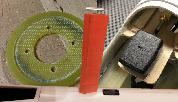
Here is the equipment mount I built. It holds the Swift, GPS antenna, and my remote antennas for regular RX. The unit bolts to the bottom of the fuselage. More connections to the back of the fuselage than the front so I wanted to have the main RX and everything attached to it in the back end.
The trays for the parts have a 1mm deep indent to keep the parts all aligned.
Leave a comment:
-
Here is another Paradigm fuselage installation example.
Leave a comment:
-
I still have more work to do on the sailplane. They shipped a roll of gap seal tape. This is the real spendy stuff from Airstore.eu. It is a 5M roll of the 10mm wide gap seal. So it's enough to do the wing but not quite enough to do the elevator. And it is not wide enough for the rudder. The stuff goes on pretty well. I'll tape each end to minimize the risk of ripping off the tape when pulling the wing in and out of the wing bags.
Leave a comment:
-
First flight today. No GPS gear in there yet. In the sub 50 temps, the GM 18x13 on the motor was reading about 65 amps static. So plenty of power available. It should go up once temperatures get warmer. I flew it unballasted around 5kg so I could still throw the model. The range check was good and the hours of radio setup all looked like they were moving the right way.
It was one of those throw it and it goes up and really very minimal elevator trim changes in the flight modes. The documented setup delivered what I expected. Control input response is similar at all the different speed settings. Nothing crazy at high speed and thermal handling seemed good. It was nice to be greeted by some morning light lift right after shutting off the motor.
Leave a comment:
-
I put an 18500 battery pack in under the wing. There is a dual battery zepsus switch in there, one that passes through the ESC and one that connects to the extra battery. I set up the YGE controller to 8.2v so it should always be around there. Alarm is set down 7.8v which should happen a little while after the ESC stops delivering any power. I also have an alarm on the motor battery voltage, but nothing will happen if the YGE just stops working and stops feeding telemetry. The main RX is towards the back of the wing and the antennas exit just behind the wing. A second remote RX is up at the back of the nose cone for some more antennas up there.
The radio setup data is pretty time consuming to input and check. There are 6 different flight modes. If you look at them, they appear really well done. The dual rates and mixes and travels adjust with the flight modes so the stick response should be consistent. And they are all in degrees so it's easy to set up your favorite angle measurement widget. Mine is a home brew with two sensors. Unfortunately one set died so I had to do one side and then check the other side.
The plane is setup in Albatross but I haven't mounted the GPS unit or Tek probe yet. Otherwise it's ready for a flight.Leave a comment:
-
The rudder and elevator servo are a simple install. Cut a hole in the tray and drill some servo screw holes. Pushrods get trimmed to length and the threaded end gets glued on. The biggest wait is epoxy curing. I do crimp the brass a little for mechanical plus JBWeld. This is a lot easier than working on a 2PK. There is a lot of room to get to the pushrods in comparison.
The hole for the wing wing wiring also needs to be cut. You just have to cut out the middle enough to feed all the wires through. I relieve the edge of the 6-pin connector a little. Two quick swipes with a plane to put a bevel on it. Then I glue it in place with hot glue. The hot glue has a little flex and adds some strain relief to the wires too.
Leave a comment:
-
Other measurements.
Tip panel 1552mm
Center panel 1838mm
Fin 515mm
Stab 660mm
The fuselage can be taken apart The nose comes off and the fin comes off. They provide a plastic piece to protect the rudder pushrod when you take the fin off.
Boom with pushrod protector on. 1600mm
Fuselage with nose on and spinner. 1972mm
Fully assembled fuselage and fin/rudder. 2056mm
So you need 2.1M in your car/van/trailer for an assembled fuselage and teh center panel is pretty large too.
Leave a comment:
Leave a comment: