

 Tweet
Tweet
Did I tell you I love this plane?
-
Len Buffinton
Team Horizon Hobby -
So then the steering system started to be a problem.
We needed real positive steering since we work in close to people and on hills quite often. The standard setup was good, not great. I moved the clevis hole in to get more throw, therefore putting even more stain on the servo and the arm. After breaking the third servo, (not cheap ones either), it was time for a solution. Enter, Scot S. ( Stew2 )
Scot designed a housing to work with the servo saver out of a Losi off road truck front wheel steering system.
We ordered the parts, Scot cut the metal, put it together and delivered it to me for installation. Understand, this is a prototype... Well, its been in the plane since day 1 and has NEVER failed. The steering system went from a problem every time out to not event thinking about it anymore. Thanks to Scot !!!
THE PARTS
THE UNIT THAT BOLTS TO THE FIREWALL
THE FINAL PRODUCT
Len Buffinton
Team Horizon HobbyComment
-
Oh, I forgot to mention the plane has a LOT of power!!!
Len Buffinton
Team Horizon HobbyComment
-
Scot, can you post the drawing and any pictures you may have on the servo saver? I thought we did at one point.
Now if we can figure out how to stop it from rolling down the hill while waiting for someone to hook up the sailplane?Len Buffinton
Team Horizon HobbyComment
-
And, Scot, are you accepting orders for 111 versions of your masterwork? I have just the airframe to give it a home!Team PowerBox Systems Americas... If flying were the language of men, soaring would be its poetry.Comment
-
Let me know if you have drawing and a parts list, it would be great to install one in my Bidule as well.Comment
-
We just fabricated Snatch's nose gear set up this weekend, post some pics Snatch!
Jeremy and Ben
SCC AAA TT TN
Comment
-
Sir! Show simple sweet servo saver setup! Len, maybe you could attach a mechanical brake to your front wheel similar in design to the DuBro item. http://shop.dubro.com/p/e-z-brake-sy...r_brake?pp=12#
Comment
-
Bidule Steering Servo Saver
The steering servo saver for the Bidule is based off of the steering servo and servo saver used in the Losi 5ive T 1/5 scale racing truck. When the Biduleish idea of moving to these tow planes was getting kicked around, there was an immediate trepidation with the durability of the tricycle nose gear and associated steering system. It is very common for the European guys to be flying from paved or at least golf-course grade flying fields. Not always the case here stateside. The original light bulb flickered on the ride back from Icare with 3 Bidules and an Arcus in the trailer. I thought there had to be a size and weight similarity between the big brother Bidule 170 and the big arse R/C cars that guys with big harry ones race. After doing a little research/Youtubing, I was watching 40-50 lbs. R/C cars being driven at 50 MPH over 10-15 foot jumps and typically landing nose first with wheels turned…. If that wasn’t similar to my typical landing, I didn’t know what was, so ding went the light and I figured if I could mount whatever they are using to steer that truck in the Bidule for a steering system, there should be a chance that it will survive. Thank God for Al Gore inventing the internets and the obsession of the human race to have to publish every last spec and detail of information available. The initial research was to learn the construction and parts of the biggest, most popular, R/C truck available, the Losi 5ive T. The parts listing for that truck is attached and studying it is an exercise left to the reader.
The prototype units built for the Bidule were all manufactured using pretty basic tools. I do not have a metal working shop, so all the parts were designed with simplicity and features that could be obtained from the tools I had on hand. All machining is done via die grinder with a cut-off wheel, a drill press and a disc sander. A #6-32 and M3 tap along with a counter bore are as sophisticated as the tooling gets. The design could be made much more elegant if designed for any level of machining beyond the cave-man method. Please feel free to take the concept and alter as desired for application or fabrication liberties.
The screen shots of the aluminum parts hint at how they go together and show the important dimensions. Any missing dimensions are not critical and should be determined for your own enjoyment, besides, that way you can say it is different and we don’t have to enter an 8 year legal battle for patent infringement since I will be retiring off of the royalties of this widget…..NOT.
Probably the biggest detail that is not illustrated is how I set the end play of the servo saver and the spacing for the aluminum parts. The unit is designed to bolt to the aft side of the firewall by using longer 5mm screws than are supplied in the Bidule kit for attaching the nose gear nylon block to the forward side of the firewall. With the longer (M5x 35mm) screws extending out the back of the T-nuts, the unit can be slid onto those protruding screws and mounted with M5 Nyloc-nuts. The vertical spacing of those screws is about 2 3/8 inches (I say about only because it is best to measure yours and adjust accordingly). To avoid interference with the horizontal legs of the mount that hold the servo saver post, the post is “lengthened†by 3 or 4, ¼†SAE flat washers. SAE washers are held to a tighter thickness tolerance and got me to the desired 2 13/16 inch spacing (correlate this to the 3 1/16 dimension on the assembly sketch, 3 1/16 – 1/8 – 1/8 = 2 13/16). When you have the servo saver parts in hand, you will see that the end play of the servo saver on the shaft is about 1/8â€. This is not acceptable, so a 3/8†flat washer was drilled out to fit over the end of the pivot shaft and thinned slightly with a little “rubbing down†with sand paper on a flat surface. This 3/8†flat washer is the common thick one that you find in the pick-a-bin at any hardware store, not an SAE one, they are thinner than the common grunt ones used on swing-sets.
I am putting my Bidule and associated servo saver together now and found that the linkage from the servo saver to the steering arm on the nose gear can be made up from the same linkage set sold for connecting the servo to the servo saver. And speaking of servo, the unit is designed around the monster Savox 236MG servo that the 5ive T guys are running. Again, going back to the abuse dealt to the truck when racing and jumping, I figured they have to use a tough servo also. Could a smaller servo be used, probably, but I figured the gear train of the Savox servo must be tough and I didn’t want to hear Len cry about any design iterations. Of course the real story is that the unit was going to be first placed into service at a full aero-tow event that I was attending and I didn’t want the tow plane to be down, forcing me to fix it and NOT to be able to fly gliders!!
So, here is the list of Losi 5ive T parts that will make up 1 servo saver with a few parts left over for a second, so if you want to combine orders with fellow Bidulies in your area, it could work:
Qty – 2 LOSB5900 Servo to servo saver linkage set (Qty is 2 to allow for linkage to nose gear from servo saver, so Qty of 2 does 1 airplane.)
Qty – 1 LOSB2550 Steering arm bellcrank (does 1 airplane)
Qty – 1 LOSB2553 Servo saver (does 1 airplane)
Qty – 1 LOSB5970 Servo saver bearings (Includes 4 bearings, enough for 2 airplanes)
Qty – 1 LOSB2551 Servo saver post (includes 2 posts, enough for 2 airplanes)
Qty – 1 LOSB2549 Servo saver aluminum arm (does 1 airplane. There is a plastic version of this in LOSB2550, which could probably be used and this one not ordered, but that has not been proven in the field yet).
Additional Hardware:
Qty – 6 #6-32x ½†Flat head machine screws (3 each for mounting the 3/8â€x 1 3/4â€x 1 9/16â€) servo mounts to the top angle. 2 screws from the back, 1 from the top)
Qty – 1 M5x20mm Flat head machine screw (second screw for mounting pivot post)
Qty – 1 M4x35mm flat head machine screw (for mounting linkage from saver/steering bellcrank to nose gear at the bellcrank end)
Qty – 1 M4 Nyloc-nut (used on end of M4x35mm screw above)
Qty – 6 M4 flat washers (used as spacers for linkage from saver/steering bellcrank to nose gear at the bellcrank end)
Qty – 4 SAE ¼†flat washers (used for pivot post end spacing)
Qty – 1 3/8†flat washer (used to set servo saver end float)
Qty 4 – M5 x 35mm Socket head cap screws (used to mount nose gear nylon block to firewall and replaces 4 screws supplied in kit)
Qty 4 – M5 Nyloc-nuts (used on protruding nose gear mounting screws to hold servo saver unit to firewall)
Qty 1 – 2â€x 2†x 1/8†Aluminum Angle stock (Only need about a foot, but you’ll probably have to buy a 2’ piece)
Qty 1 – 3/8†x 1 ¾†Aluminum bar stock (Only need about 4 inches, but you’ll probably have to buy a 2’ piece. I had to order from McMaster Carr, I don’t think Home Despot or Blowes carries such a size)
Hopefully, between this winded wisdom and the attached pictures that you can get the idea at least of what we are doing. Feel free to ask any questions, I’ll do my best to answer…
One last item, you will definitely want to replace the steering arm on the nose gear shaft supplied with the kit to one made from 1/8†or 3/16†steel angle iron. The stock piece won’t stand a chance against this grunt of a mechanism.
The author would like to thank his Mother for all the time spent drilling 2 digit integer addition into his brain, for without that, I could never have hammered this thing out of such fine wrought iron.Last edited by Stew2; 02-24-2016, 10:49 AM.Comment
-
The Losi 5ive T parts list pdf is to big to attache so here is the link:
Comment
-
Originally posted by Steve P View Post
I'll have to noodle on this a bit to see what I can come up with for the 111 size. I think the 5ive T based design is to big for the 111.
Len, Bob, You guys tried a smaller Turnigy servo saver that wasn't up to the job on the 170, but any thoughts on that size for the 111??
Steve,
Len does have another prototype that I put together, it could be used for sizing to see how much room it takes up in the 111. I still think the 5ive T based saver is to grunty for the 111 though. I think it would push failure into the side plates that the nose wheel gets mounted on, but it could also be that if the situation drives failure into those plates that we have much bigger problems to solve, like how to get all that dirt out of the engine....
Just rambling thoughts, but surely open to helping find a solution for the 111.
Does Stephane have any comments back on the 111 durability and system??Comment
-
Love that last Pic From Jeff with the storm rolling in.
Comment
-
Originally posted by Steve P View Post
Ok,
I did a little digging on these here internets and I found that Losi also makes 1/6 and 1/8 scale trucks with a servo saver of the same basic design as what we used from the 1/5 scale truck. So, I have parts identified if you want to go forward with this.
My gut feel is to use the parts from the Losi 1/6 scale Audi IR8. They sell the servo saver in more of a kit format, so the part numbers are:
LOS251030 for the servo saver kit
LOSA6946 for the servo saver bearings
LOS254024, LOS255006 and LOS253011 for the linkages
The rest will be manufactured from aluminum stock similar to the 170's design.
That would at least get us started.Comment
-
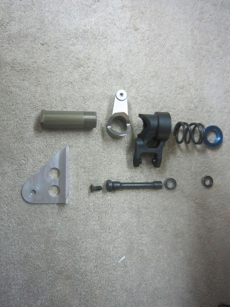
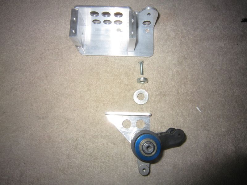
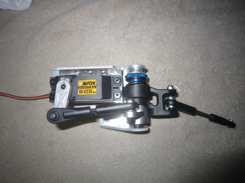
Since I was at the final assembly stage of my Bidule steering servo saver I snapped a few pictures to show all the piece parts and how they fit together. It should allow you to pick out the pieces from all the parts ordered and show the parts that were hand made from aluminum.
Ok, so not all the hand made parts are aluminum, here is the new steering arm made from 3/16" thick 1 1/2 x 1 1/2 steel angle iron. I enlarged the arm plan form a bit to make it somewhat lollipop shaped to accommodate the larger 4mm bolt used out of the second servo linkage kit from the Losi parts.
Next is the top frame piece. Made from 2" x 2" x 1/8" aluminum angle. Cut to length with a cutoff wheel in a die grinder and the edges finished on a disc sander and a little filing. All the holes are just simple drill press work.
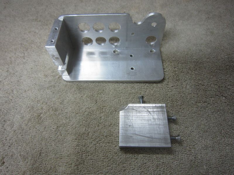
Here is the bottom bracket and all the Losi parts that get bolted/assembled to it. You can see the wedge shape of the two mating bell crank arms that work to compress the spring as the servo saver during a shock load. The blue knurled nut adjusts the tension of the spring. I believe Len found that his was cranked down half way or more when finally tested by turning the nose gear. There is a lot of leverage from that nose gear!!
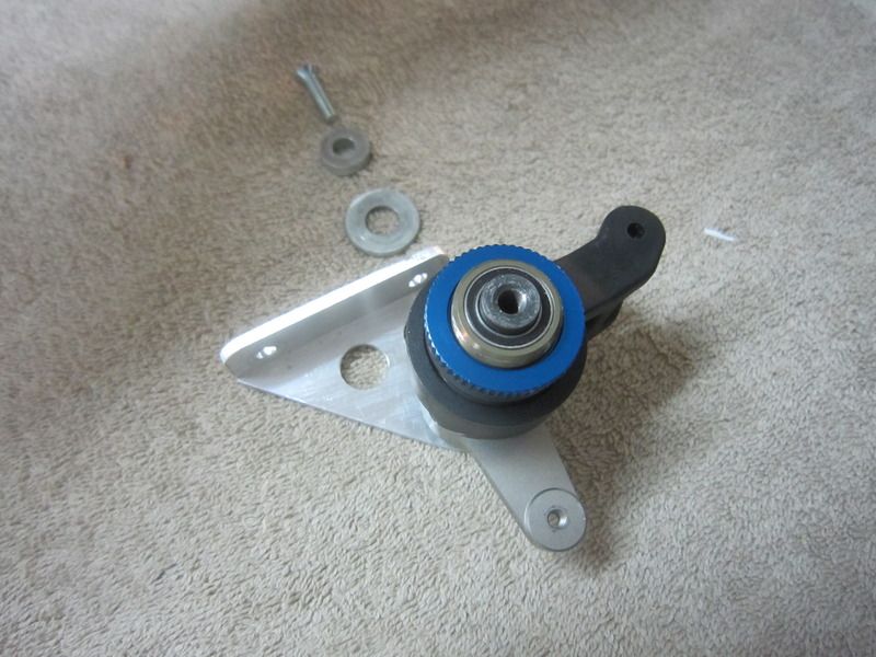
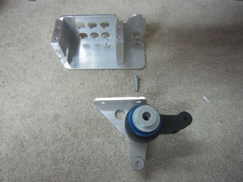
Now with the steering rotating assembly complete, mounted on the bottom frame piece and the large washer for end play adjustment and the smaller washer stack for spacing the frames apart enough that the nose gear nylon block bolts will fit inside the frame.
All lined up to hint at the assembly order.
Here the washers are stacked for assembly. The large 3/8" washer fits over the end of the shaft and the smaller 1/4" washer stack. All ready to accept the top frame and 5mm flat head screw to tie it all together.
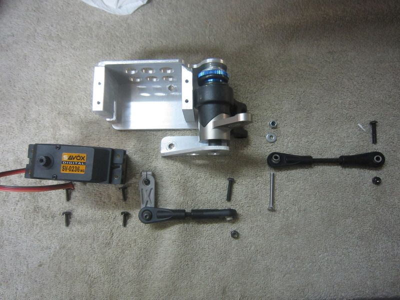
With the frames assembled to the servo saver, it's time to bring in the linkages and servo. When I tighten the top screw holding the top frame to the pivot post/bottom frame assembly, I start with the pieces vertical and just snug up the top screw. Then I lay the assembly with the backs of the frame pieces on a flat surface and final tighten the top screw. This keeps the two frame pieces aligned making a flat surface that will go against the firewall at installation.
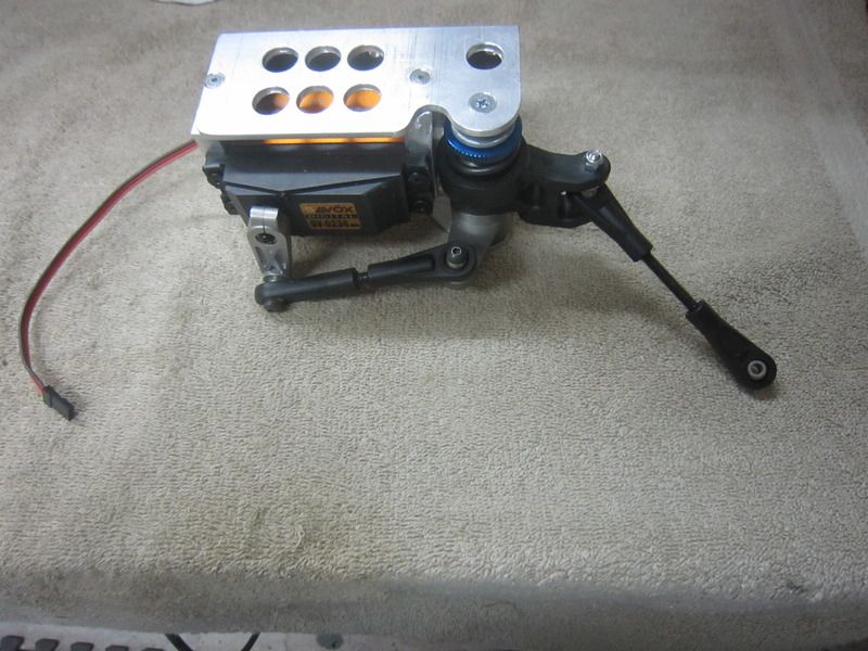
Here is the firewall side of the assembly.
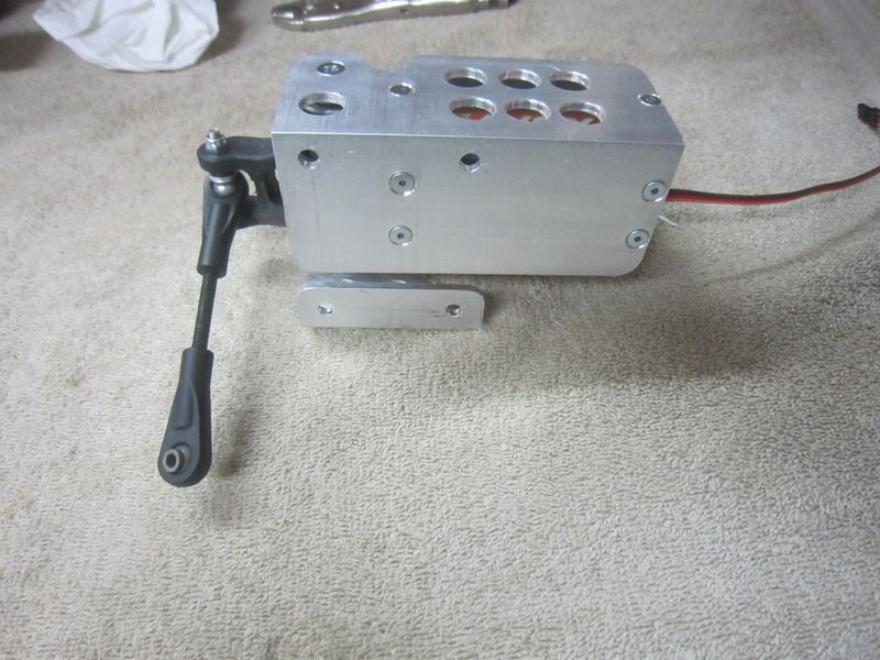
The assembly turned over:
And now ready for installation in the fuselage.
To be continued.... apparently I can only put in 10 photos in a post. No big deal, just a rule to know.
Comment
-
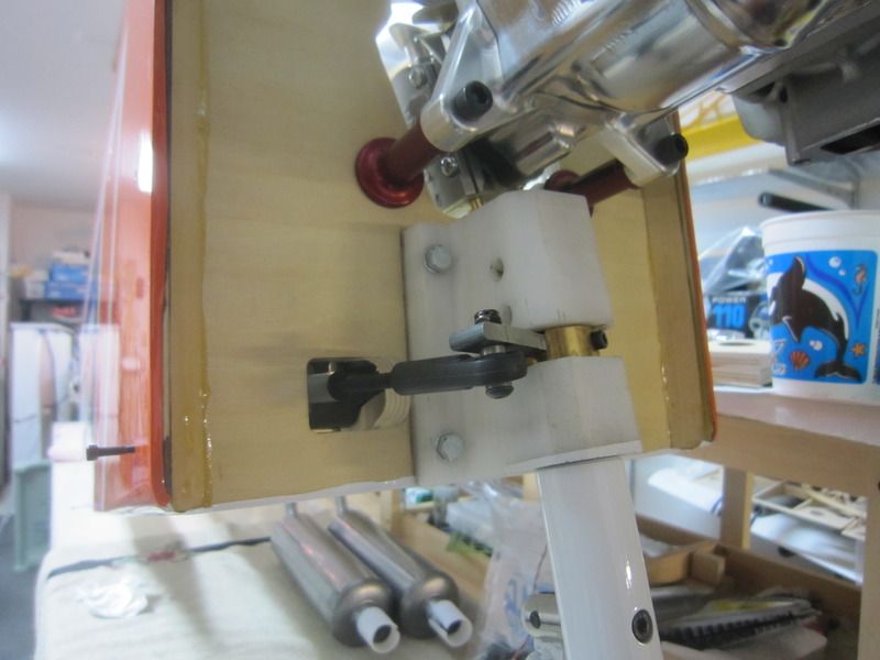
See, I wasn't going to just leave you hanging there, wondering what this mouse trap looks like in the line of duty:
Assembly in the fuselage is a bit more of a dance than we would really like, but so far it has been a one time deal. There certainly are design changes/improvements that could be made to make it more of a modular unit, but I'll leave that refinement as an exercise for the student....
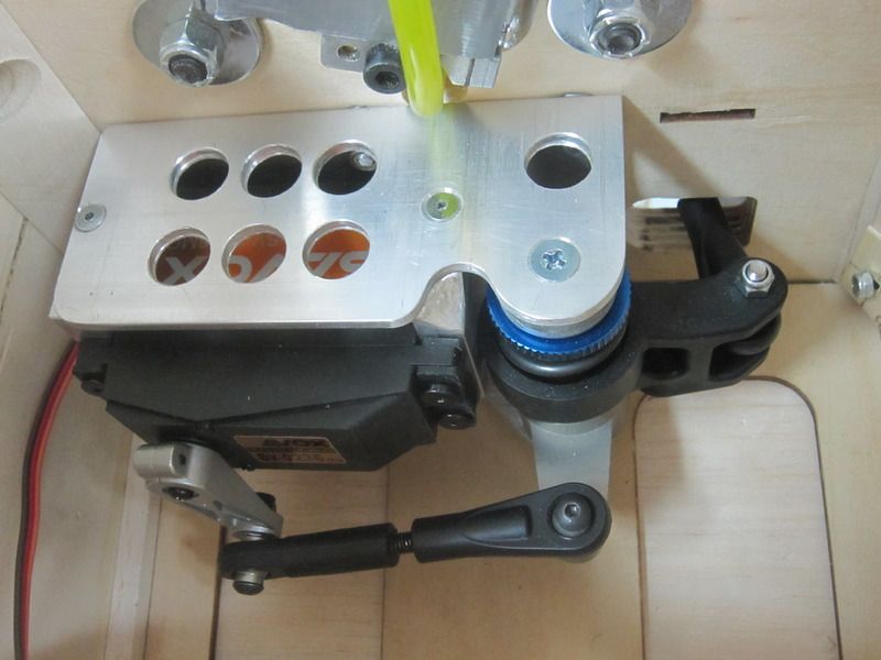
One last photo to show how it fits on the firewall and how much of the kit internal shelf I removed for access for assembly. Ignore the small nyloc-nuts against the triangle stock reinforcing the firewall to fuse join, they are my Rube Goldberg clamping system while the epoxy dries. Ok, I can't lie, they are the Jesus pin of the fuselage, pull that out and whole thing blows apart like a house of cards.... really it does... really.
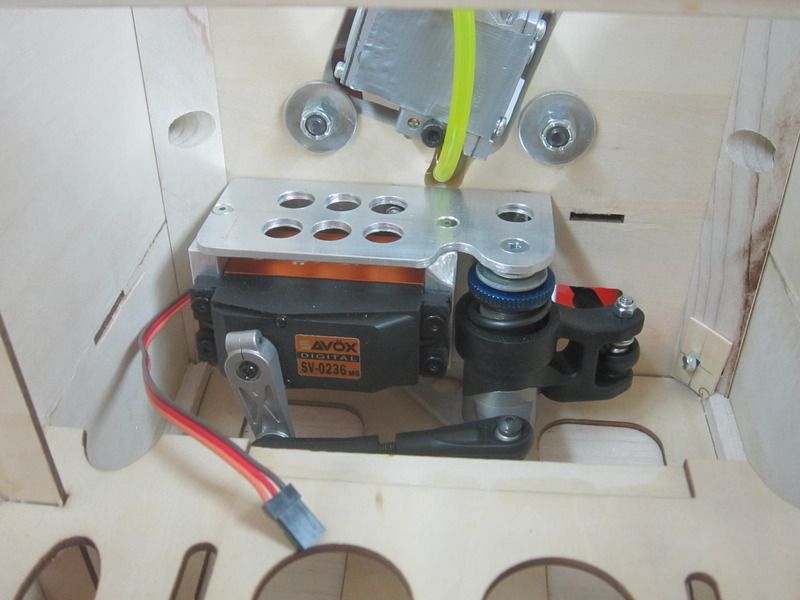
She ain't really pretty, purely form following function. Truly on the lines of proof of concept, it can be made much more elegant if desired. Feel free. Please post changes and improvements for future generations. Any questions, please ask, it is how we all learn. Here's to good steering and continuous towing!!
Scot
Comment
Comment