Announcement

Collapse
No announcement yet.

TopModel Bidule 170 ~ build thread by JimD

Collapse
X
 
  • Filter
  • Time
  • Show
Clear All
new posts

  • TopModel Bidule 170 ~ build thread by JimD

    StephaneR (aka French1) made us aware of the success of the Bidule design in France and that set in motion a group order from TopModel. After Len's Bidule 170 (with ZDZ-180 engine) went into service this summer, it became crystal clear that this model is the current segment defining aircraft for aerotowing. We really need to thank BobM for putting together the group buy through ICare that brought the first of these planes into the USA. Then we need to thank ScotS (Stew) for actually transporting them from Etienne's shop in Canada to us here in the states, and of course Stephane for the idea in the first place!

    Bob has already posted extensive pictures of his build and modifications, but I am taking a little different path than either he or Len. This plane will no doubt be the subject of numerous build threads and every builder has their own ideas. This will be my take on the subject.

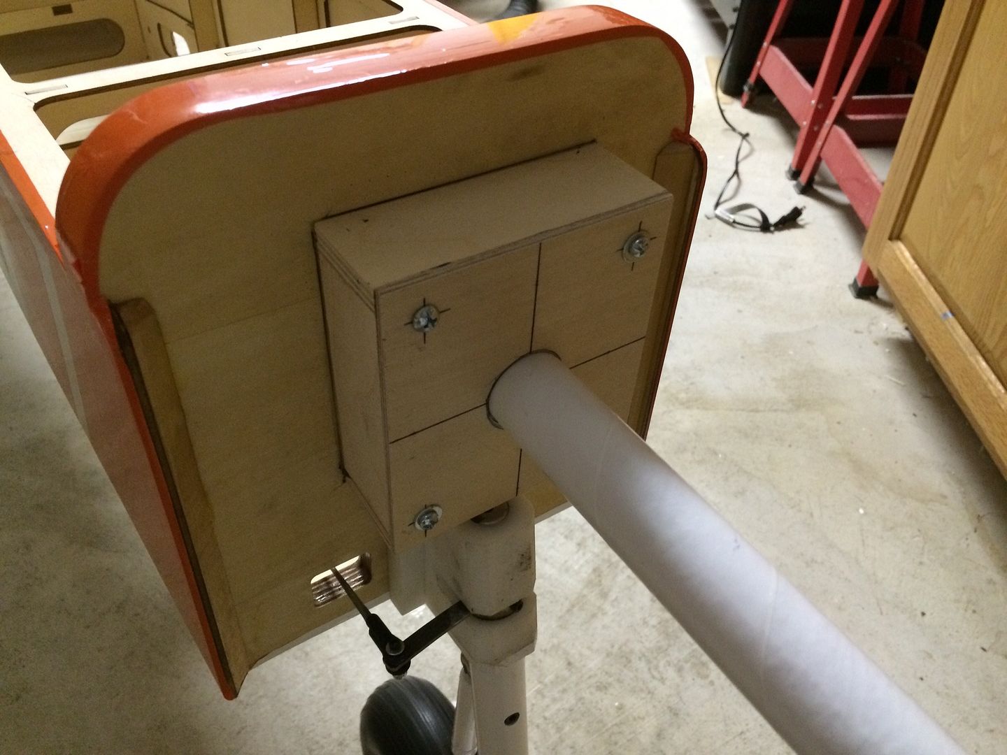
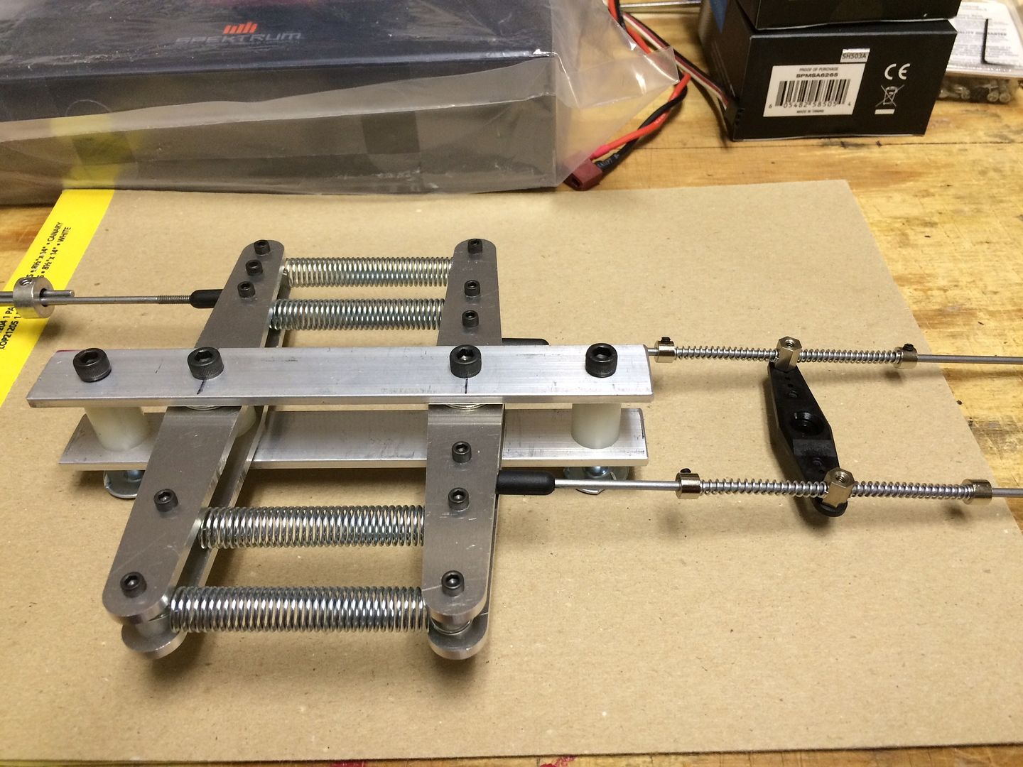
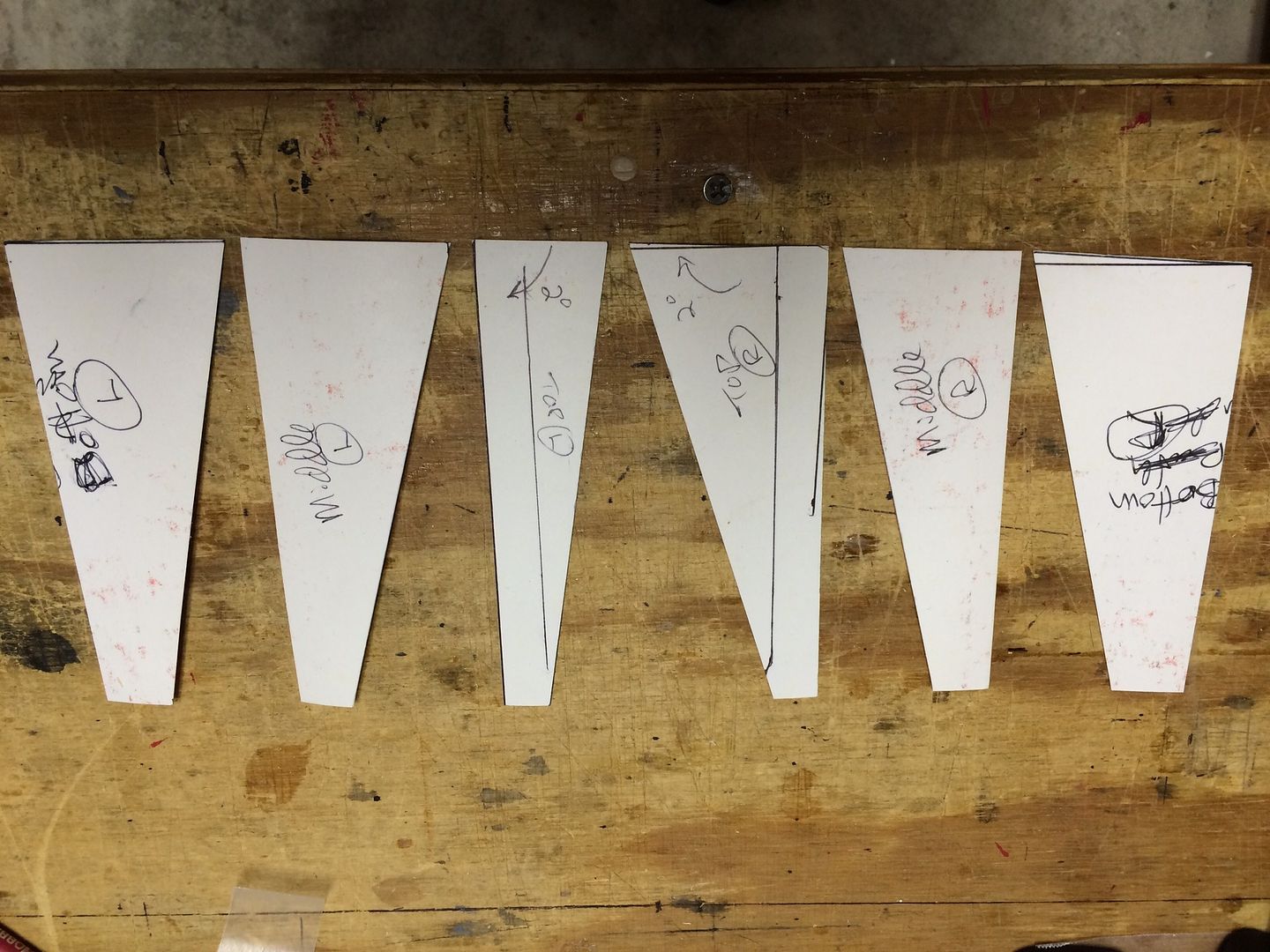
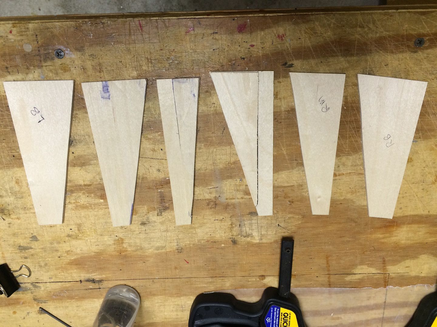
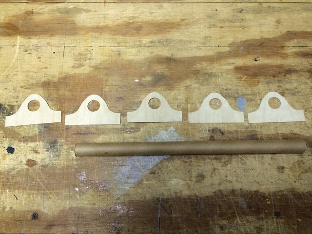
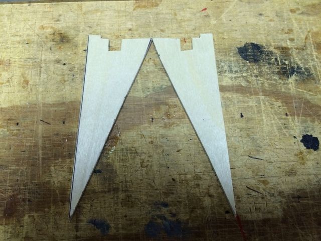
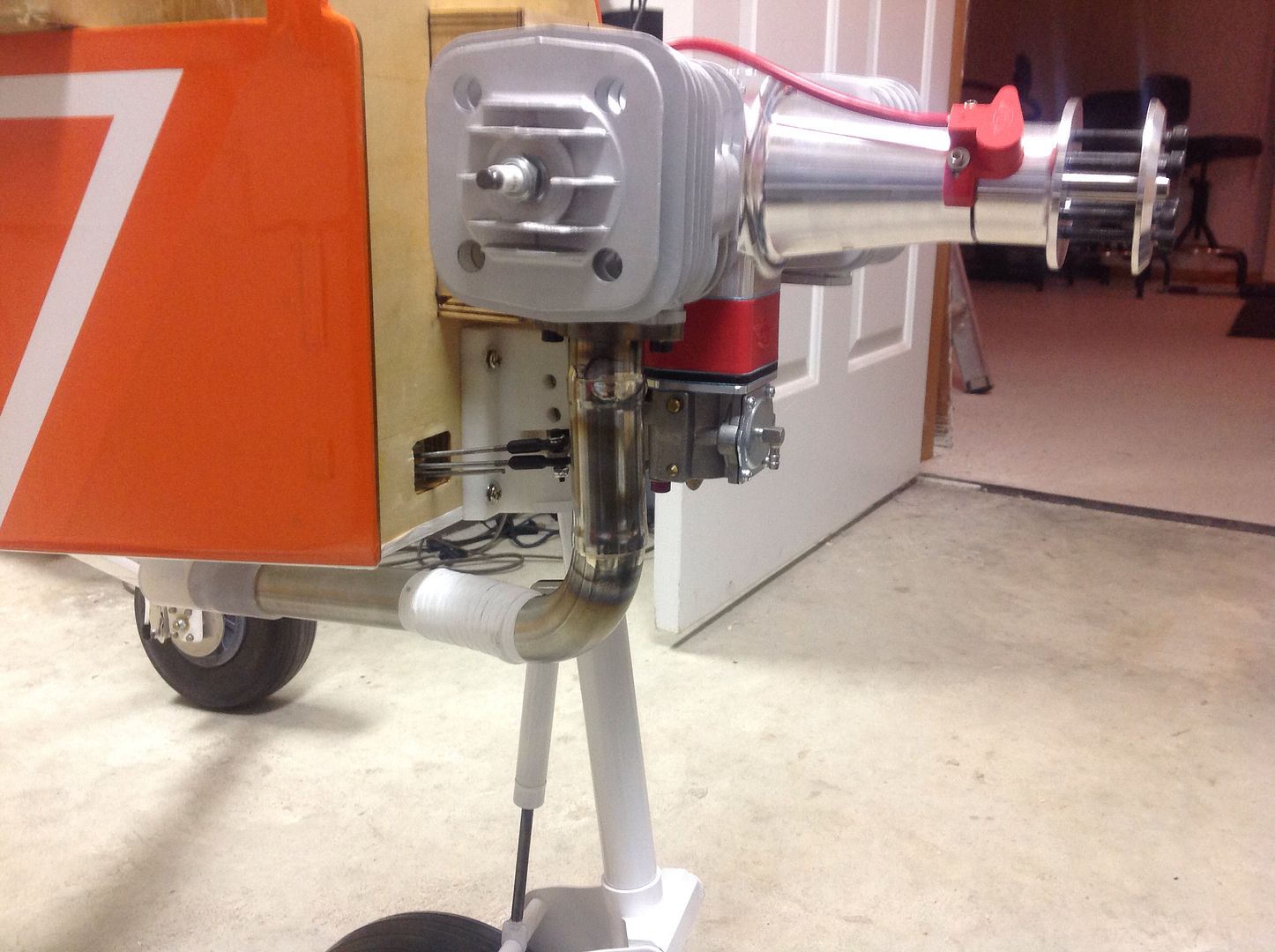
    First is mounting the engine. We have opted for a DA-170 engine to power our Bidule. The engine needs to be spaced 1-5/8" out from the main firewall and we elected to build a plywood box spacer. This method has worked very well for us on numerous other models, so we are sticking with what we know. Here are our un assembled parts.

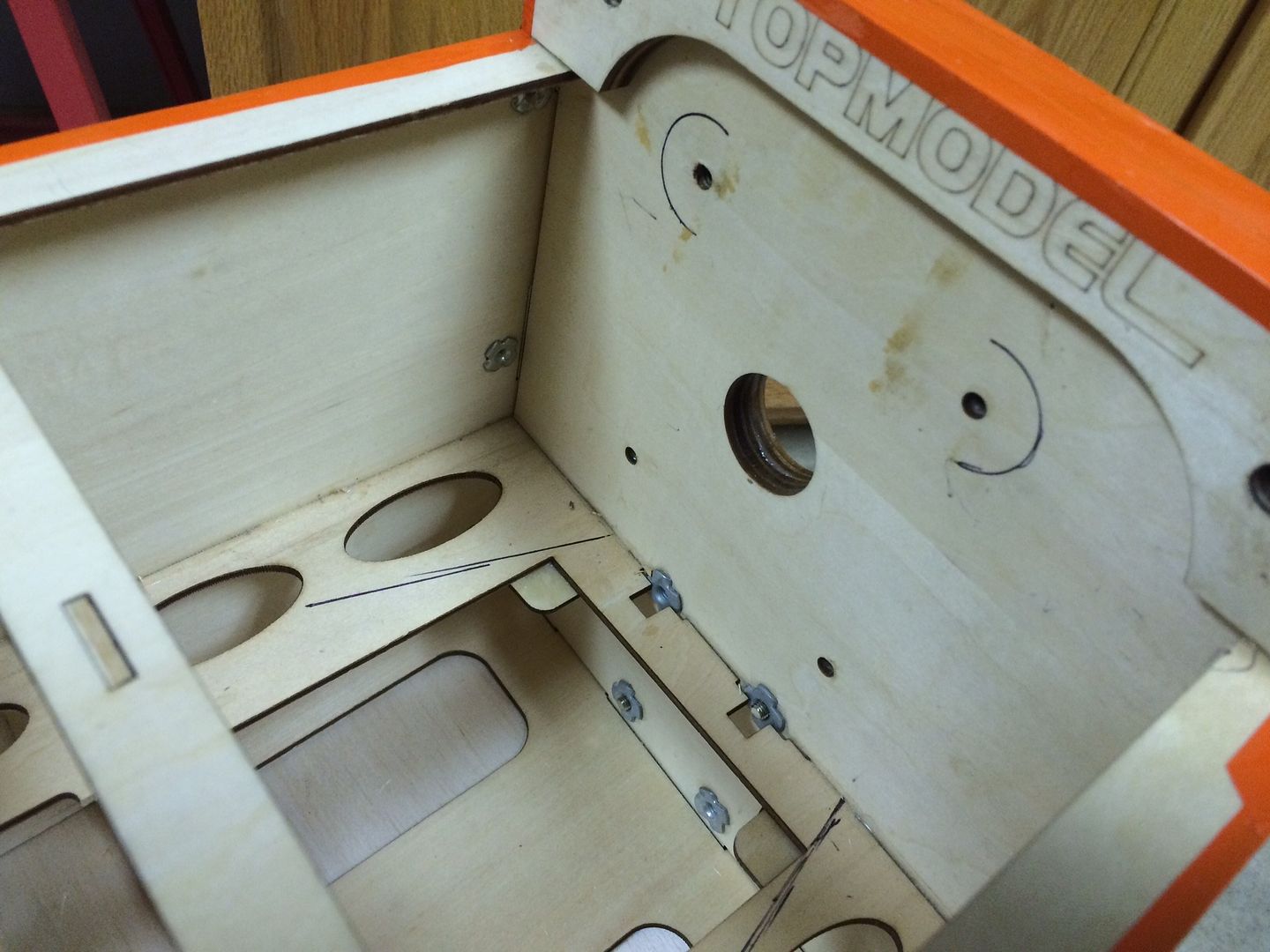
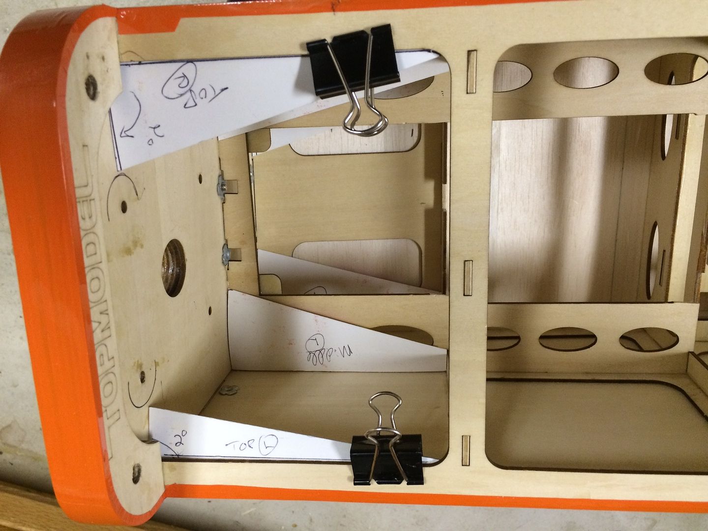
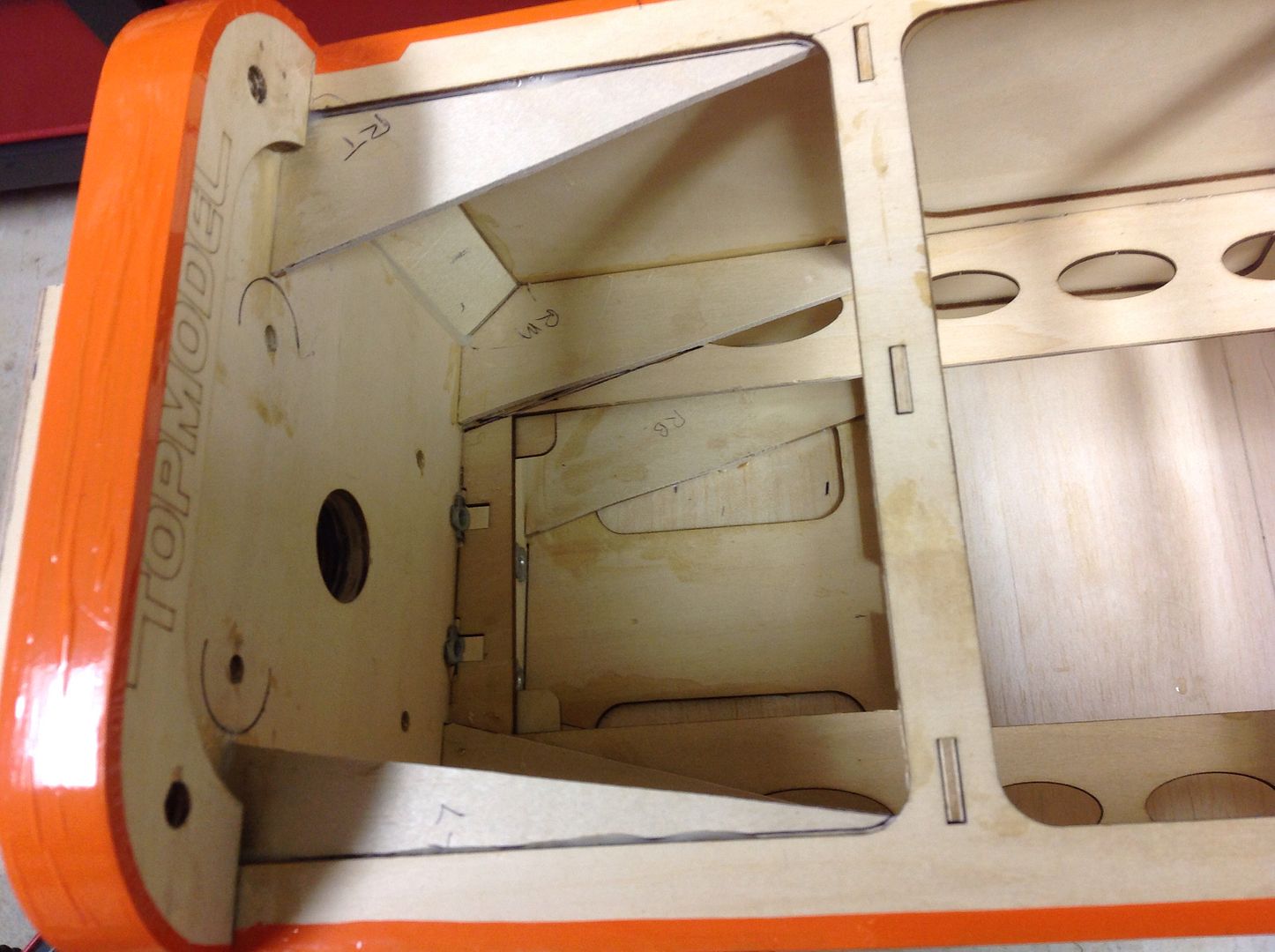
    The box is 4-1/4" wide and 4-5/8" tall.


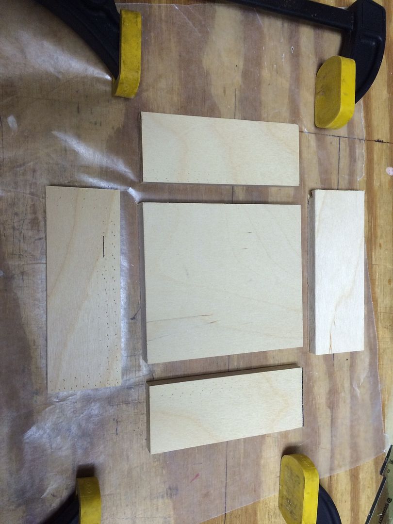
    The sides were cut to 1-1/2" wide with the firewall inset inside these side pieces.


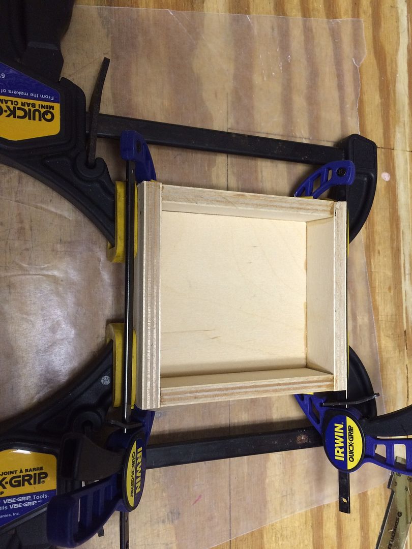
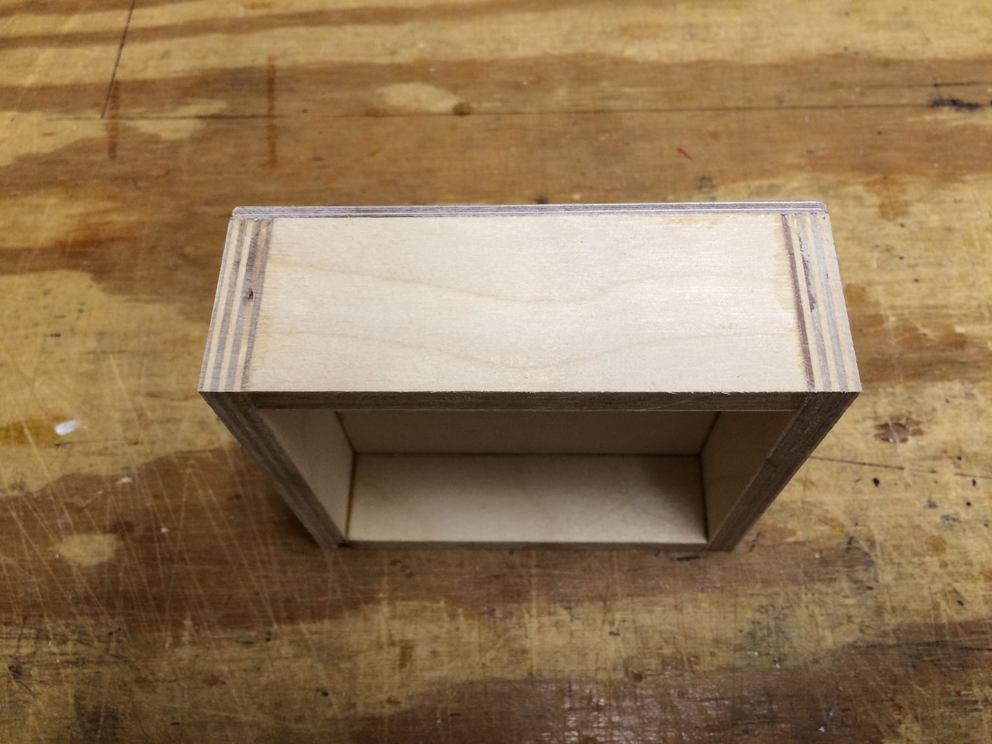
    A second layer of 1/8" plywood was added to the front of the box.


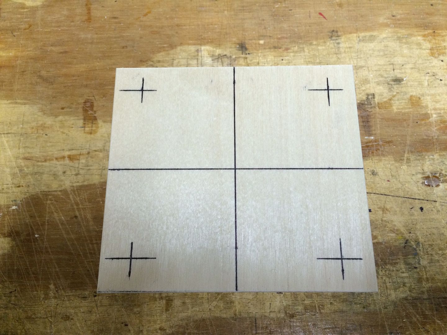
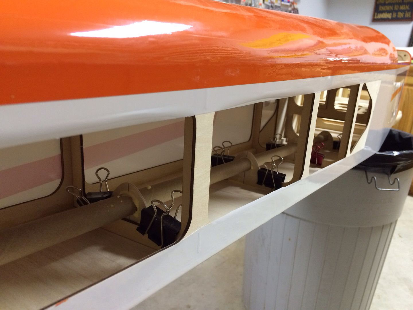
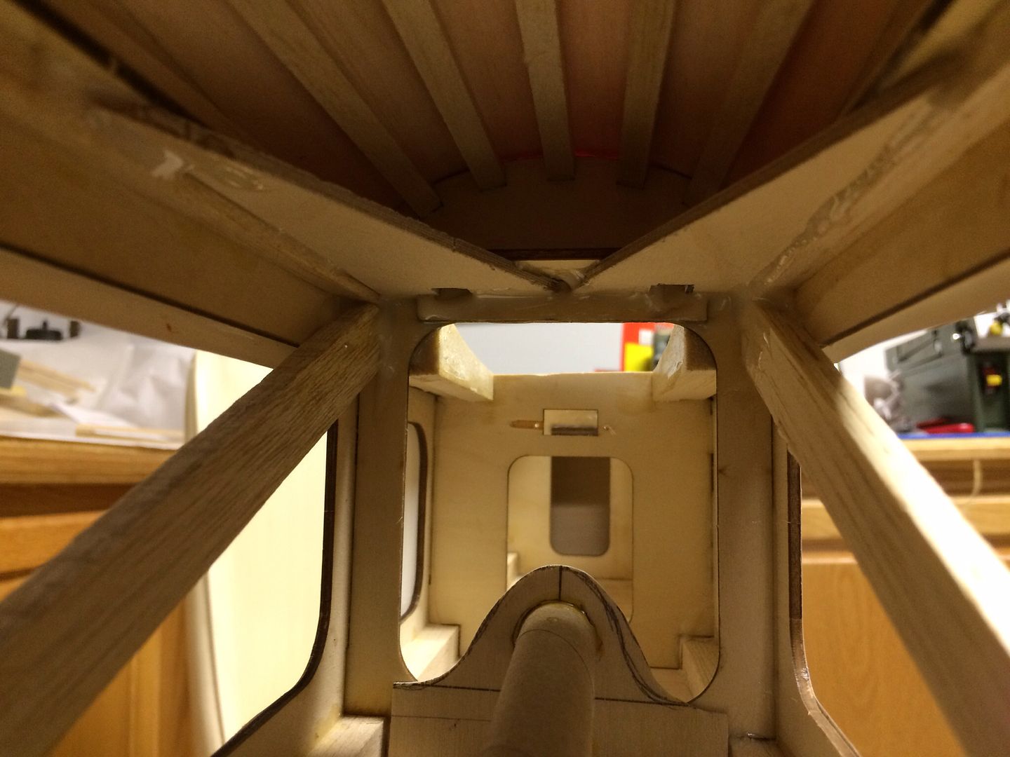
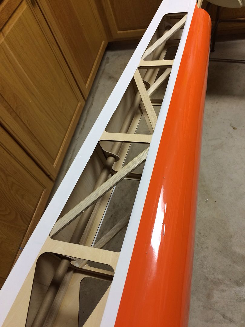
    We cut a center hole the same diameter as the one in the main firewall and inserted a cardboard tube that the ignition wires will pass through. The engine mounting bolt holes were used to secure the box to the main firewall while the epoxy cures.


    A Site for Soar Eyes

  • #2
    Every chain has a weak link, and the nose gear pushrod system is that weak link in the Bidule 170. The nose gear is massive and the wheel has a trailing arm suspension system. If the nose wheel is slightly turned (as it would be if you are holding rudder in a crosswind landing) it exerts a lot of force on the servo and pushrod when the nose gear touches the ground. Even taxiing, especially on rough ground, puts a lot of force on the steering system.

    We set out to make a shock absorbing system for the steering that would be up to the task of the thousands of take offs and landings that tow planes are subjected to. Our design involves a double Bellcrank with springs between the two. A pushrod connects the nose gear tiller arm to the front crank arm on the right side. Double pushrods connect the servo output arm to the rear crank arm. The springs in between these two cranks allow the front crank to move a fair amount without transferring the shock of that movement to the rear crank. The springs also act to keep the nose gear centered after being moved off center by the force of contact with the ground.

    As an added feature to protect the servo, the two pushrods are attached to the servo arm with an EZ connector but allowed to slip through this connector if there is a significant shock. Double springs act to center the pushrods in these connectors but allow for some slipping motion in the case of a sudden shock load.

    I made a prototype out of steel parts to test the concept and then had Gunny fabricate aluminum parts using his CAD design programming skills and his CNC router. Here is the second prototype that will go into our plane.

    A Site for Soar Eyes

    Comment


  • #3
    These new ARF sure are a snap to assemble huh Jim.
    Jim Gallacher

    Comment


    • JimD
      JimD commented
      Editing a comment
      ARF = Always Require Finesse

      😉

  • #4
    That is very impressive Jim

    Steve K
    Steve K

    Kremer Aerotowing Team

    Comment


    • #5
      Really looks great Jim ! Looking forward to seeing how it progresses.

      Bob

      Comment


      • #6
        Looking at the backside of the main firewall where it attaches to the fuselage sides and floor reveal a shocking lack of gluing surface to keep that firewall in place as the 170cc engine cranks out torque.


        The structure can be significantly strengthened by the addition of some 1/8" plywood triangles. Here we made paper patterns.


        Then we used these to make out plywood parts.

        A Site for Soar Eyes

        Comment


        • #7
          Here are the six plywood pieces installed plus hardwood triangle:


          Next step was adding a tube for the rudder and elevator servo wires.


          Covering was removed from the fuselage sides to gain access.


          Plywood braces were cut to reinforce the bulkhead at the leading edge of the stab.


          Diagonal balsa sticks were added along each fuselage side.


          A Site for Soar Eyes

          Comment


          • #8
            Assembling the fin and stab proved to be interesting. The supplied hardware was a problem in that the two screws that attach the fins were not a good fit. It seemed like the diameter of the bolts was slightly undersized. We replaced them with socket head metric bolts and things went together perfectly. Then, when the diagonal braces were installed, one of the supplied bolts would not thread down into the stab. One side fit fine and the other side just did not fit. Once again, I went to my inventory of metric hardware and found the correct size socket head bolts. The side that the stock bolt fit into was fine with this new bolt, but once again the other side was a problem. Looking down into the hole, the threads in the T-nut did not look the same as the other side. Out of frustration, we tried a 6-32 bolt and it threaded right in!!!!! So, one side was metric and the other side was English! At this point, we decided to replace all of the hardware with 6-32. We carefully drilled and taped the metric side for a 6-32 bolt and all went well fortunately. The bolt and lock nuts at the fin joint were also changed to 6-32 hardware.


            Hinges were epoxied in with West Systems G-Flex epoxy which holds extremely well and resists vibration damage.


            Our rudder servos were mounted to the stab instead of the covers.


            DuBro horns were used instead of the stock parts.


            The supplied bolts are 1-1/2" long, but we changed them out to 2" long bolts for better control hookup geometry.


            A Site for Soar Eyes

            Comment


            • #9
              The horns for the ailerons and flaps were missing from our kit, so we used DuBro 8-32 horns.


              The supplied bolts are about 2-3/4" long, but we changed them out with 3" long bolts for better control hookup geometry. I found 3" long socket head bolts at Micro Fasteners.

              Last edited by JimD; 03-11-2016, 02:18 PM.
              A Site for Soar Eyes

              Comment


              • #10
                We wanted a pushrod that is thicker than standard 4-40 so, after some searching, we ordered these turnbuckle rods. The different lengths are perfect for the flap and aileron hookups.


                In order to get them to thread into the ball link fittings, we had to drill out the hole in the fittings with a 7/64" drill bit.

                A Site for Soar Eyes

                Comment


                • Mosquito
                  Mosquito commented
                  Editing a comment
                  Jim, I'm assuming that you used the shorter of the rods for your flaps and the longer for your ailerons?
                  Tim

                • JimD
                  JimD commented
                  Editing a comment
                  Yes, there is about a 1/2" difference between the two.

              • #11
                When I got up this morning, the plan was to glue on the stab fairing that blends the fuselage into the stab. All seemed to be going well, I placed the part on the stab, traced around it with a fine line Sharpie and then used a T-pin to stick holes through the UltaCoat so the glue could grab on better. Next, I squeezed a bead of Zap Goop around the bottom of the fairing and dropped it in place. As per Murphy"s Law, it was at this point that I realized that the fairing did NOT follow the contour of the stab and no amount of pressure would make it fit down properly...what to do...take it off before the glue really takes a set.

                At this point I was so aggravated that it was time to walk away and do something else, so I went to the mountain and shoveled the dirt pile out from in front of the steps. We had to dig down into the slope of the filed at the bottom of the stairs and the excess dirt was just piled in front of the stairs.Got that job done and admired the steps for a while until I was ready to come home and start in on the Bidule again.


                The other thing that I have been dreading is making headers. The drop needed is way more that any of the stock headers. I bought 90 mm drop headers and a short length of extension pipe (65 mm long). Next, I tried to separate the flange from the pipe, but it did not want to let go so we moved on to plan B. We measured down 25 mm from the flange and cut the pipe apart, Our extension was only flared on one end, so we used a socket as a dye, hammered it into the end of the pipe and made a very nice flare. Once soldered in, we checked the fit and it looks perfect.


                Okay, now to fix that fairing...Decided to use our heat gun and soften the fiberglass part. Once it started to soften, we pushed it down onto the stab and it took a nice set. Okay, now for the glue and a second attempt...worked out very nice this time!

                A Site for Soar Eyes

                Comment


                • #12
                  Looking good Jim. Seems like one step forward and two back is common. Good to take a break. Are those disc brakes I see? Nice.

                  Steve K
                  Steve K

                  Kremer Aerotowing Team

                  Comment


                  • #13
                    Nice fix Dr.
                    See what a trip to the mountain can do!
                    Len Buffinton
                    Team Horizon Hobby

                    Comment


                    • #14
                      One of the biggest challenges of the Bidule 170 is how to control the steering function of its giant nose gear. Back when I first got my Bidule 170, Len and Scott had not yet found the steering servo saver that has proven to be an excellent fix. The off the shelf parts make their fix particularly impressive.

                      I set out to invent a servo saver mechanism and had Gunny custom cut some parts for me and now it is time to try them out. Even with Len and Scott's setup, the pushrod attachment to the tiller arm exerts a twisting motion on the arm and makes it prone to breaking. Their fix is to make a thicker steel tiller arm. Part of my setup is to solve this issue by using a double ball link "fork" for this attachment. Hopefully, this will avoid the twisting stress.

                      Well, here it is:


                      Seems to work good on the shop floor, we will see...
                      A Site for Soar Eyes

                      Comment


                      • JimD
                        JimD commented
                        Editing a comment
                        March 2017 update:

                        The HS-7954SH servo was not adequate and was changed out for a Spektrum S9020. See post #24 in this thread.

                        As for the tiller arm, the twin ball links have worked perfectly and the stock tiller arm continues to serve without failure.

                    • #15
                      I don't think it is a twisting motion that fatigues the tiller arm as much as it is vertical force components that will bend the arm back in forth resulting in a fatigue crack at the thinnest ligaments across the lower screw hole. Your design should allow the best alignment to minimize or eliminate the vertical movement. Time will tell. I could also be that the material that the stock arm is made of is such crap that it is un-fixable with that piece. Bob, Len and I went with the grunt solution of throwing more section and better material at it. Will you be running 7.4V at the steering servo? I ask only because I am curious as to how much torque your system will be running with. Always great to see, learn and think from different designs and solutions. Your design would be much easier to fabricate than the Losi servo saver adaptation. The servo access and serviceability is much better.

                      Comment


                      • JimD
                        JimD commented
                        Editing a comment
                        March 2017 update. My stock tiller arm has not failed in 50+ hours of operation, so my hypothesis seems to have been proven true.
                    Working...
                    X