
 Tweet
Tweet
After having lost a few threads...due to technical difficulties. I thought I'd start a generic thread on this new forum for all to use.
-
-
I am not going to do a complete build thread again on my Carbon Cub. The model has been flying for close to a year now. Just to review...mine is the Red Version of the Aeroworks 40% (100cc) Carbon Cub. Mine has an older DA150, running MTW 110 front dump canister mufflers and a 28.5 x12, three blade Mejzlik carbon fiber prop with a 4.5" Dave Brown aluminum spinner. Fuel is supplied from a 100 oz. main tank with and 8 oz. header. The fueling connections are from Jersey Modeler.The model is flown with a Spectrum DX18v2 transceiver with a Spectrum AR12120, 12-channel DSMX PowerSafe receiver on board. I am also flying with a Spektrum TM1000 telemetry module and an electronic kill switch. All servos are Spektrum A6030's. On board power is from two 6000 mah Lipo packs for the radio system and a 4500 ma Nimh 4.8 volt pack for the electronic ignition. The tow release was ordered from Iflytallies. I ordered the Aeroworks custom wing bag set as well as the Aeroworks 8.25" tires. I also ordered the accessory instrument panel, but when I got my model it already had one in the cockpit. I ordered Carbon Cub logos and registration numbers from Cali Graphics.
More to come later......Last edited by Xroadie; 08-20-2015, 03:39 AM. -
Many thanks for starting this again !
I just received my Carbon Cub about a week or so ago, also red and white color scheme.
I'm thinking of a set-up very similar to yours, but using the JR DMSS system that has XBus for servos and receivers.
Pete.........any thoughts or suggestions are very appreciated on this. I know you and others (Len) have built these and are really knowledgeable about the airframe and construction that works for this one.
Many thanks !
BobComment
-
Hi Pete.
Thanks for starting this new thread, it makes a lot of sense.
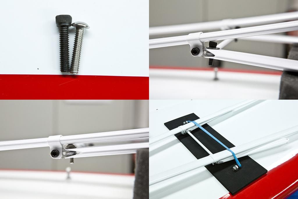
The item I would share is the wing struts. The struts have weak bolts in the base where they connect to the fuse. Just about everyone I know who have built and flown one has had the strut bolts break. This, if left unchecked, will lead to certain wing failure in flight.
The fix is to drill out the end of the strut and remove the strut bolt. Remove as much material ( wood ) as necessary to create a cavity. You will upgrade to a larger bolt and epoxy it in with JB weld. You'll need to re-tap the fitting to match the upgraded bolt.
NOW,
You need to sand or file the INSIDE of the fork fitting that bolts to the fuse. The idea is to make it large enough for a sloppy fit. Your bolt that attaches the strut to fuse tang should be left loose with an elastic stop nut so the who fitting is loose and movable. This way, when the wings flex, which they will, the strut fitting has room to move without breaking.
So far, this has been working well on mine.
LEN
Len Buffinton
Team Horizon HobbyComment
-
In between taking care of things around the house and my children I have been able to make some progress on my Carbon Cub.
I make a carbon fiber hatch cover that will set just aft of the wing. Len did this and it is a great access point for the batteries and electronics. I used a layer of heavier fiberglass as a base layer and then 4 layers of carbon fiber. West Systems 105 resin with the 206 hardener. The plate worked out well, it was made on top of the fuselage as a form using duct tape as a base and release agent......works really well. The basic shape is completed and cut to size. I sanded lightly on the edges and also slightly round the corners. The final cutout for the tow release will be done once I have the release installed.
I've clear coated the top with a couple coats of the 105/206 resin thinned a bit. This has filled in the weave really well so the final finish will be a high gloss. Some wet sanding to smooth it out really well and I'll wait to do the final gloss coat once the cutouts are completed and the cover is fully fitted to the fuselage. I have a hatch release that Len told me about, one that are commonly used on rc marine boats. Should work well. I also found another company called Quick Latch that has some nice latches as well. I picked up one of the smaller Quick Latches to see if the size would work at all, but I think it is probably too large for the plane.
I have started working on the wiring needed for al the servo and other electronic connections.....Hansen Hobbies has a great line of connectors and sets for this. I like the locking connectors for the wings....a 6 pin locking connector makes it easy to plug in the wings and not worry if the right connections are made or not.
I'll use the new XBus system for this plane. I have dual infinity XBus receivers that go into a heavy duty redundant center hub. Then use the XBus servo servo adapters or converters. I have 2 XBus 4 lead adapters and 1 converter 4 lead. This allows me to use both XBus servos as well as conventional digital servos. For all the control surfaces (ailerons, flaps, elevators, and rudders) and the tow release I have the new JR NX8921 XBus servos, The throttle, whole, and electro optical kill switch are conventional. Likely JR DS9411HV servos for the throttle and choke.
Here are a couple pictures of the electronics....packaged and neat :
And all out and now programmed for the initial installation into the Carbon Cub (final programming will be completed after everything is in place and I can set the correct throws and other adjustments). There are 3 harnesses coming off the center hub. I have programmed the XBus harness on the left to be all the wing servos, NX8921's (R and L ailerons and R and L flaps). The center XBus harness is for the tail servos, NX8921's (R and L rudder and R and L elevator. The harness on the right is a converter harness for using conventional digital servos and it will run the throttle (DS9411HV), choke (DS9411HV(, tow release (NX8921), and onto-electical kill switch (Evolution EVOA100). Batteries are all Duralite EXB 5200mAh, square packs for the receiver and servos and a flat pack for the ignition that has a Castle Creations regulator set to 5.9v.
The set up for using the XBus is a bit confusing at first. I have programmed the converter harnesses for using digital servos on my sailplanes and it was pretty straight forward with the hand held programmer from JR. The XBus harnesses aren't programmed, but rather the XBus servos themselves. Took me a few tries, but I think I have it figured out for now. The servos are now individual specific to each of the functions once programmed, so it is important to keep them numbered and match the lead number with the servo on the XBus harnesses (I am certain there are others that know the XBus system and programming better than I do and may have an easier way to get it working......I have to share that the instructions included with the harnesses and servos didn't give very clear steps or instructions as to how to set things up on the system IMHO).
I'll start working away on installing the electronics as time permits over the next couple days or so. I should have the majority of the work completed sometime early next week.
Power is the DA 150 with MTW front dump canisters. 3 blade prop, either a Mejzlik 28.5 x 12 or an Air Models 29 x 12. 100oz main tank with a header tank of about 14oz I think will do it for fuel.
I'll post more pictures as I make progress here.
BobComment
-
I had an issue when flying my CC a few months back in Georgia at the Southeast Regional Aero Tow. It was the first time I had flown the CC on a hotter day. I would do a tow or two and then my throttle would start walking all over the place at lower RPM....then go dead stick. I would land and could not restart the DA150. I tried several fixes at the field with no results...other than flying with the cowling off, which seamed to remedy the situation.
After talking to Desert Aircraft and a consultation with Peter Goldsmith, the problem turned out to be that the carb was over heating and going into vapor lock. The cylinders were getting enough cooling air, but there was an eddy of sorts around the carb. The fix was simple....I opened up the chin scoop in front of the carb as well as the two lower cheek air exits just behind the carb. It's working great now!
PeteComment
-
Many thanks for the information on that one Pete.
Working away here slowly on mine. I have all the tail servos installed and finishing up the wing servos. Wiring is loose for now as I will cut to length and add the ends once I have everything in about the right placement.
Need to install the bed over the floor of the fuselage where the gas tanks will be and then install the receivers and associated equipment on the upper fuselage floor. Finally I'll get the tow release plate and servo in place and add a floor in the cutout I am making behind the wing area. Batteries and switches will be there.
Hope to make some good progress tonight after dinner and see where I end up at the end of the evening.....hopefully I'll be about ready to start work on installing the engine and working on the headers and canisters.
I'm thinking of installing an aluminum plate on the backside of the firewall. My thinking is that it will distribute the load from the bolts and mounting of the engine more evenly across the plywood firewall plate and make it less likely to get crushed right where the bolts go through for attachment........I will think have to about that more a little later after I get other parts done here.
Might be ready by Labor Day weekend if I keep at it here.
BobComment
-
Making some progress here.
I have all the control surface servos installed now and the rough wiring completed. I still need to install the receivers and duo center hub. They will go in after I have the engine, headers, and canisters installed (I have to build a floor where the fuel tanks will go, on the base of the cockpit floor over the canisters. I want to make sure everything fits before I start installing the floor and then the radio equipment.
I have the engine trial mounted now using an additional backplate that is installed inside the firewall box. The ply is 3/8" and the aluminum plate is 1/8". I decided this would be a good way to distribute the stress of the mounting bolts across the firewall, and also help prevent the plywood firewall from being crushed by the bolts.
The fit is pretty good and I think the engine has a very solid mount now. I'll use some washers and lock washers along with nylon insert lock nuts to hold everything together.
I'll have to finalize the mount and I'll also fuel proof the whole wood engine mounting area with some thinned resin to make sure everything is sealed well.
The engine, headers, and canisters are for tomorrow night. Once they are in place properly I'll start completing the fuselage floor and the rest of the radio installation.
BobComment
-
Happy to make one Pete, I'll see what I can do over the next week or so and then I'll mail it out to you. PM me and I can get the specifics from you for getting it to you.Comment
-
Bob,
What did you use to cut the carb clearance hole in the aluminum sheet?Comment
-
Hi Asher,
I marked the hole to match the existing one in the firewall on the fuselage. I then used a drill press and made a series of smaller holes through the aluminum that were close to each other and close to the scribed circle. Once that was done I used a fine metal blade in my jig saw to make the cut around the circumference. I cleaned everything with a round file to very close to the scribed line and then finally used a drum sander on the drill press to make the final adjustments and also round over the outside exposed edge.
Once the ply and aluminum are glued to each other (with medium CA) I went back and made sure of the fit to the existing firewall. The inside has tri stock so I had to carefully adjust the final dimensions of the plate to match with a tight fit. Once that was done I held it in place by hand and used the mounting holes I made in the existing firewall as guides for drilling them into the new backplate. I did that on the drill press using a 17/64 drill bit as I am using 1/4 - 20 mounting bolts for the engine.
After the mounting holes are drilled it is ready to be installed on the back of the existing firewall with resin. I use the mounting bolts and nuts to secure everything in place and tighten things down and let the resin cure overnight to make a solid firewall in the end. I put a bit of vaseline or similar on the bolts where they go through the holes to prevent the resin form adhering to them.Comment
-
Thanks Bob, a lot of work. I like your idea of the plate so I'm thinking I'll try one on the Bidule. May try a hole saw in the drill press for the carb hole though.Comment
-
Thanks Bob...if I was starting mine now ....I would take you up on the offerOriginally posted by BobM View Post
I cut a couple pieces of aircraft ply, one for the top bolts and another for the bottom bolts on my Carbon Cub. I made them mainly because the spacing of my DA150s mounting bolts came out right next to the triangular stock on the back of the firewall, leaving no room for fender washers. If I had your patience I would have tried to fit a one piece plate like you did, but it was quicker for me to fit two "half" plates instead...your idea is better!
I mentioned that and posted photos in my original Carbon Cub thread.....I DO NOT want to recreate that entire thread....I may just make a gallery with all the build photos from the original thread and share the link.
A couple other things we talked about was if you plan to fold the struts against the wing for transport, the bolts supplied for part of the strut assembly will not let that happen, unless Aeroworks has changed them, you will need to. I can't remember all the specs as far as bolt size goes, but here is a pic from that.
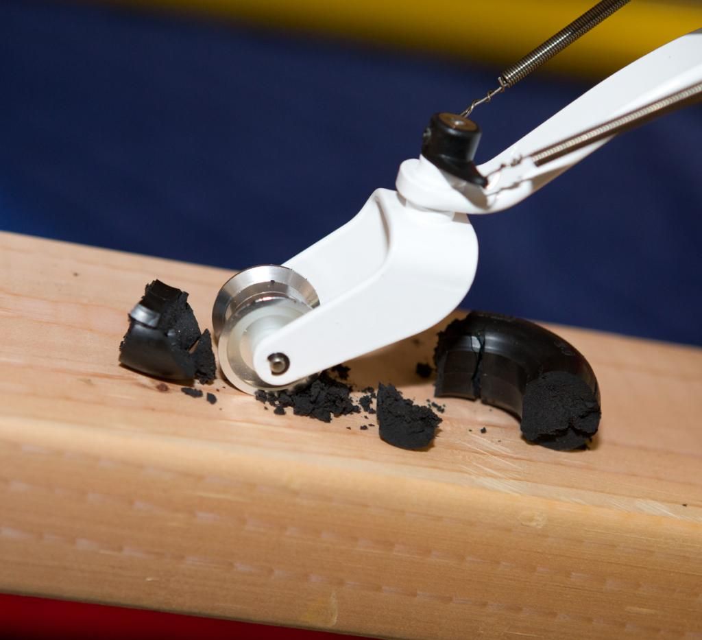
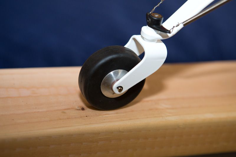
The other thing was tail wheel axle and the tail wheel itself. First my original tailwheel tire, crumbled to pieces during assembly of the model and was replaced with a Dubro wheel and tire. Also the c-clips that are on each end of the axle WILL come off. You can solder them on are you use a long bolt with safety nut.
The Dubro wheel....note C-clips on end of axle.
 Last edited by Xroadie; 11-16-2016, 02:21 PM.
Comment
-
Really great information, many thanks for sharing the changes and photos........extremely helpful !
On my Bidule I didn't make a solid plate, but rather I used some strip steel from Home Depot and made 2 strips that then are vertical in the backplate. This seems to work very well when I flew the Bidule last weekend, a very solid mount along with the new aluminum mount that was made for me for the engine itself.
Working away on the Carbon Cub a step at a time here. I hope to get some work completed on the headers and canisters tonight. After those are sorted out it is just a matter of finishing all the rough wiring and finalizing some of the placement of various electronics.Comment
-
Engine is mounted and on to the headers and canisters tonight.Attached FilesComment
-


Comment