Announcement

Collapse
No announcement yet.

Bidule 111 v2.0

Collapse
X
 
  • Filter
  • Time
  • Show
Clear All
new posts

  • Bidule 111 v2.0

    What a difference a year makes!

    On 5/21/2015, I started a build thread of my recently acquired Bidule 111 which can be found here: http://forum.scalesoaring.com/forum/...553-bidule-111

    The build was underway and then the flying season started and I got to see Len's Bidule 170 in action...uh oh...I wanted one!

    As things turned out, Stephane was wanting a Bidule 111 and Len was facilitating another ICare order, so I sold my partly completed Bidule 111 to Stephane and ordered a Bidule 170.

    By the time I got the Bidule 170 and started the build, it was October 2015. That build thread can be seen here: http://forum.scalesoaring.com/forum/...thread-by-jimd

    The Bidule 170 was completed for the start of the 2016 season and now has 60 hours of flight time. It proved to be everything I had hoped and more, so naturally we ordered a second one and the build on it is underway.

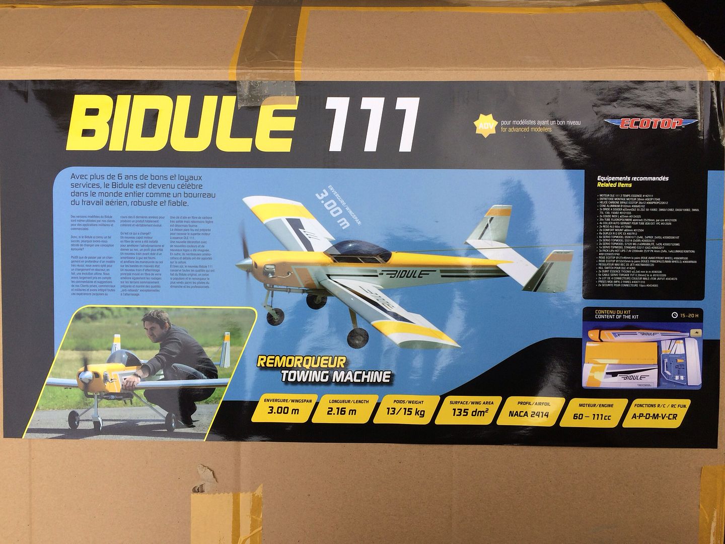
    Meantime, watching Stephane fly his Bidule 111 and hearing reports of Kris flying his Bidule 111 and still having a brand new DA-100 sitting on a shelf in the shop, the decision was made to get another Bidule 111 for those occassions when something other than the big guy is needed. Anyway, welcome to the Bidule 111 v2.0 build.
    Last edited by JimD; 11-19-2016, 02:25 AM.
    A Site for Soar Eyes

  • #2


    The first thing that caught my eye upon opening the box and pulling out the instruction book was this insert.


    Sure enough, as the parts were unwrapped, some nice updates were found.

    The rudder servo bays and covers have been completely redesigned. The covers are now made out of fiberglass.and are attached to a plywood mounting frame. This assembly sits down into a recessed pocket in the underside of the horizontal stabilizer.


    Another update is the nose gear assembly. It now has bushings in the side frames where the pivot and axles bolts go through.

    A Site for Soar Eyes

    Comment


    • #3
      The tiller arm looks like it is made from a heavier stock and appears to be stainless steel. There is also an aluminum disc on top of the gear leg to prevent it from pulling down and out of the Nylon mounting block.


      The previous steering pushrod was truly a weak link...the new design servo saver is a much larger version of what we used to put on throttle servos.


      A Site for Soar Eyes

      Comment


      • #4
        Hi Jim..
        It appears someone at Top Model is watching these forums and reading our threads. Good for them to step up and make changes.... Thats a good manufacturer.

        Love the changes to the rudder servo attachment covers and the tiller arm. The bushings are great additions also.
        Len Buffinton
        Team Horizon Hobby

        Comment


        • JimD
          JimD commented
          Editing a comment
          Agreed! Whether it was this forum or another source, glad to see the improvements. these are great airplanes already and this only makes them better.

      • #5
        Another improvement is the addition of a brass insert into the horizontal stabilizer to reinforce the hole that the hold down bolt goes through. I like to use a socket head bolt with a neoprene bonded steel washer for these attachments, fortunately, the washer fits down into the brass fitting.

        A Site for Soar Eyes

        Comment


        • #6
          The new steering pushrod and servo saver looks interesting, but the one thing I do not like is the small ball link used for the tiller arm attachment. First of all, the hole in the tiller arm measures 3.90mm.


          Secondly, the diameter of the bolt for the ball link measures 2.82mm so that is going to be a sloppy fit, plus, this joint is going to take a lot of abuse and the small bolt just does not look up to the task.


          DuBro makes a very robust 6-32 Monster ball link and the 6-32 bolt measures 3.42mm. The ball link is also design to thread onto 6-32 size threads.


          The new pushrod is made from thick wall aluminum tubing. We carefully drilled out one end and cut 6-32 threads into the hole so a 6-32 stub can be threaded in. The plan is to JB Weld this 6-32 stub into the end of the aluminum tube and use this pushrod assembly for our connection to the steering servo.

          A Site for Soar Eyes

          Comment


          • #7
            As a matter of personal preference, the stock hinge points were replaced with Robart Hinge Points, 1/8" size for the rudders and 3/16" for all other surfaces. We like to prepare the holes with a Dremel tool so the tapered shaft of the hinge point recesses into the holes easily. Before gluing these parts together, we like to assemble the parts dry for a test fit to confirm a good parts fit. We also like to do one side of the hinges at a time. Usually, we will install the hinge points in the fixed side first, and once that epoxy sets, join the movable surface side to finish the process.

            Note that we paint the fingers in the hinge section of the hinge points with Vaseline so epoxy will not stick in this area.


            As for hinging, I like to use West Systems G/flex Epoxy because it clings to the parts really well, resists vibration damage, is easy to mix 1:1 ratio, and has a fairly long pot life so you can do a lot of hinges at one time. We mix a small batch in a medicine cup and use a wire wand to dip into the epoxy and then plunge it down into the holes. We finish by painting a slight amount onto the hinge points before pushing them into the holes.

            Last edited by JimD; 11-20-2016, 10:22 PM.
            A Site for Soar Eyes

            Comment


            • #8
              Are you going to use RE-2 tuned pipes or canisters?

              Comment


              • JimD
                JimD commented
                Editing a comment
                Hi Kris, this is going to be a Clark Kent version... DA-100 with MTW-75 rear dump canisters. You have the Superman version with the DA-120 with RE-2 tuned pipes!!!

            • #9
              Hinging is completed and control horns installed. We decided to use the included hardware horns for the elevators, but replaced the rudder horns with DuBro Heavy Duty Control Horns .40-.91 size.. Once we started to make the rudder pushrods, we discovered that the stock horn bolt was a little too short for a nice straight connection. Since all of the longer socket head bolts are not fully threaded, we substituted this Phillips head screw.


              We used servo tape to affix the rudder servos in place and then epoxied in hardwood blocks. A screw was place through the cover from the outside into the hardwood blocks to help keep them secure. The servo was then screwed to the blocks.


              The servo leads were shortened to avoid having excess wire coiled up in the stabilizer. We have used Hansen Hobbies tools and connector parts with excellent results over the years.


              This old servo burned up its insides, but it makes a great drill guide for preparing servo mounts. Once the holes are drilled, they are reinforced with thin CA.


              Building season has definitely arrived!!!!!

              Here is the view from my deck this morning:

              Last edited by JimD; 11-21-2016, 11:01 AM.
              A Site for Soar Eyes

              Comment


              • #10
                looking good Jim! Hope to have a bidule some day too.. I like your idea of servo tape and mounting screws on hatch style servo mounting....looks like you could slope right off your balcony!

                Matt

                Comment


                • JimD
                  JimD commented
                  Editing a comment
                  Hi Matt,

                  My house is on the same mountain range as the HighPoint Airfield with the same westerly view. Just a little further north from the field location. It is 11 miles door to door driving, but less than half that distance by air. Something about my DNA makes me like mountain tops!

              • #11
                Next step was to make a Y-harness for the rudder servos. This was incorporated into a Multiplex 6-pin connector so only one electronic connection is needed for the stabilizer to fuselage connection. Esprit Model sells Jeti MPX Soldering Couplers that make the assembly of these connectors both easy and durable. You can also see the screw through the fiberglass door into the hardwood servo mounting blocks.TopModel has incorporated pre-cut slots for the Mulitplex connector using the Multiplex connector housing.which can be seen in the picture below.


                We used the supplied string to pull the completed Y-harness assembly through the stabilizer.


                Wire harness installed and ready to hook up rudder servos, now on to making the rudder pushrods.


                Final assembly of servo mounts and rudder pushrod installation, nice straight connection.

                Last edited by JimD; 11-21-2016, 11:12 AM.
                A Site for Soar Eyes

                Comment


                • #12
                  Moving on to the wings, time to make the servo extension leads. We will again be using the Multiplex 6-pin connectors to simplify the connections between the wings and fuselage. TopModel also has included a slot in the internal framework for the mounting location of these connectors.The wing needs a 38" extension for the aileron servo and a 12" extension for the flap servo to extend from the servos to the MPX connector. 16" leads are needed to extend from the fuselage 6-pin MPX connector to the receiver. This is how we make them.

                  First, we plug a pair of the MPX 6-pin connectors together and add the MPX Solder Couplers Servos boards.


                  Next, solder everything together and tin the wire lead pads.


                  Then prepare the wires by stripping about 1/8" of the insulation.


                  Add solder to tin the bare wire ends.


                  Now solder the wires to the boards.


                  We use Y/R/B and W/R/B twisted wire so it is easy to tell which lead goes to the aileron servo (White) and which to the flap servo (Yellow). Note that the 3-wire leads to each servo are separate, they do not share the red and black power leads.


                  The MPX Installation Connector Housing for the fuselage side needs to be trimmed out a little to allow the connector board to slide through.


                  Finally, add the heat shrink to hold the wires in place and insulate the connections.


                  Custom wing servo leads completed. Now on to adding the individual servo connectors using our Hansen Hobby parts and tools.

                  Last edited by JimD; 11-23-2016, 02:27 PM. Reason: Added links
                  A Site for Soar Eyes

                  Comment


                  • #13
                    We will start with the wing side first, adding the connectors to the 38" and 12" extensions for the aileron and flap servos. Here is the step-by-step using the Hansen Hobby tools and connector parts.

                    We like to unwind a section of the wire and hold the individual wires in the order in which they will go into the connector.


                    Next, strip the ends of each wire, again holding the wires in the order in which they will go into the connector block.


                    Then crimp on the connector pins.


                    Push them into the connector block, note the order of the wires for correct polarity.


                    Add the housing and the connector is completed.


                    Double checking the polarity with a servo plugged into our newly completed connector. Black to black, red to red, and signal to signal.(in this case white for aileron servo and yellow for flap servo...all Hitec servos have B/R/Y leads, Futaba servos have B/R/W, and Spektrum/JR servos have brown/red/yellow.


                    Wing side completed and ready to install in wings.


                    Last edited by JimD; 11-21-2016, 01:10 PM.
                    A Site for Soar Eyes

                    Comment


                    • #14
                      These wiring harnesses are then pulled into the wings.


                      We like to use a one inch long piece of 3/8" heat shrink tubing to hold the servo connection together inside the wing.


                      We then made our control linkages using Hangar 9 Titanium Pro-Links, 4 inch for the ailerons and 3-1/2 inch for the flaps. These are really nice because they have right-hand thr


                      We used DuBro 4-40 Heavy Duty Ball Links on the servo side of the control rods.


                      Wings and tail feathers are now completed.
                      Last edited by JimD; 11-23-2016, 02:29 PM.
                      A Site for Soar Eyes

                      Comment


                      • #15
                        Moving on to the fuselage, we started by cutting out a section of the rear platform to gain access to the lower part of the aft fuselage compartment bulkhead.


                        We like to use the lightweight cardboard tubes, available from T-n-T Landing Products, to route the elevator and servo leads forward. mounting plates were fabricated to hold each end of this tube. On the cabin end, we used 1/4" thick balsa 6-1/4" wide by 2-1/4" tall with 3/8" notches cut into the bottom corners. For the rear, we used a 2-15/16" wide by 1-1/2" tall piece of 1/8" aircraft plywood. The rear plywood piece also acts to reinforce the bulkhead under the front stabilizer support.


                        These pieces along with the cardboard tube were glued in place using epoxy mixed with West Systems #403 Microfiber Adhesive Fillers
                        Last edited by JimD; 11-23-2016, 02:54 PM. Reason: Added links and info
                        A Site for Soar Eyes

                        Comment

                        Working...
                        X