Announcement

Collapse
No announcement yet.

Bidule 111 v2.0

Collapse
X
 
  • Filter
  • Time
  • Show
Clear All
new posts

  • #46
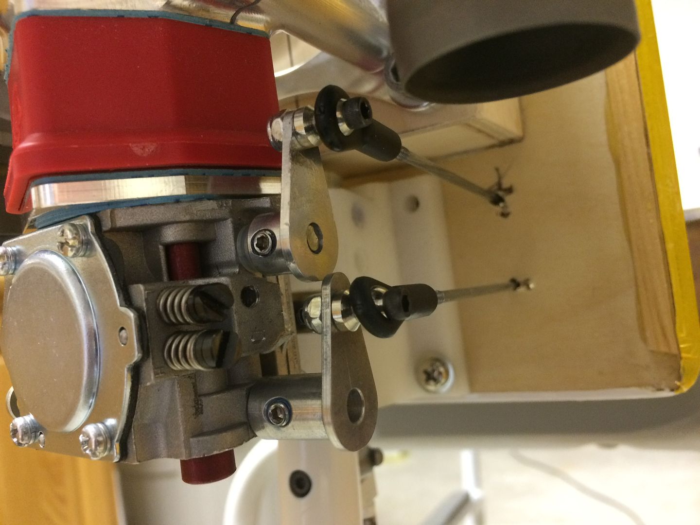
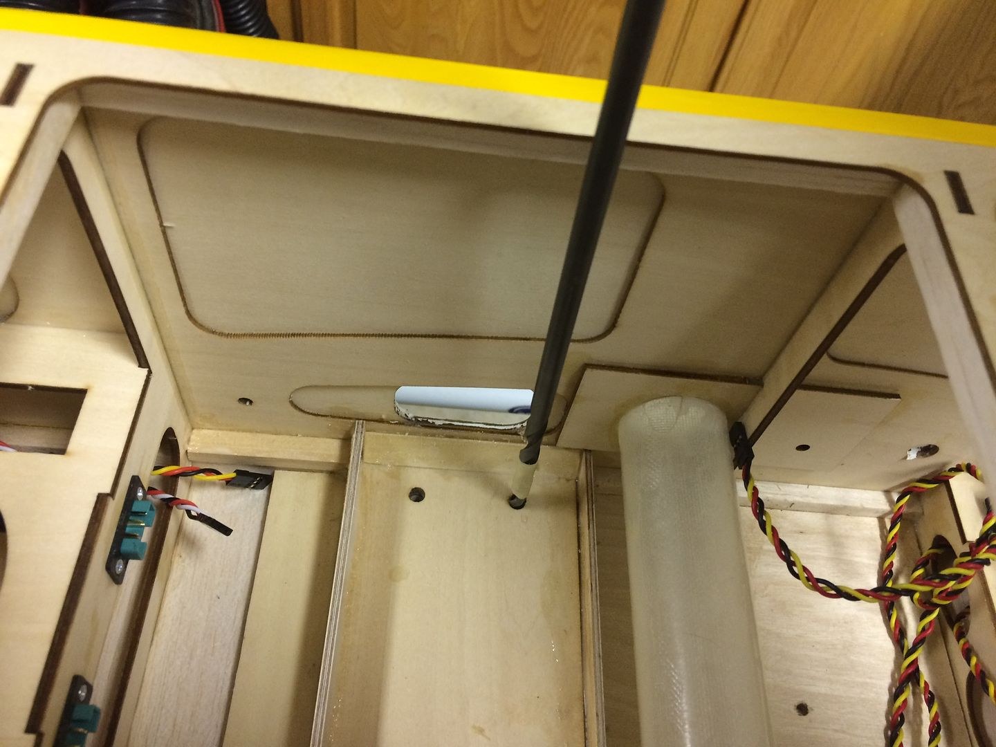
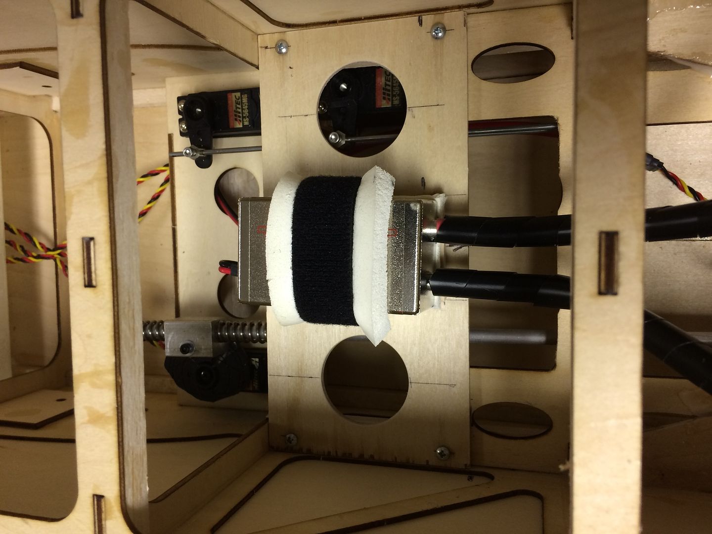
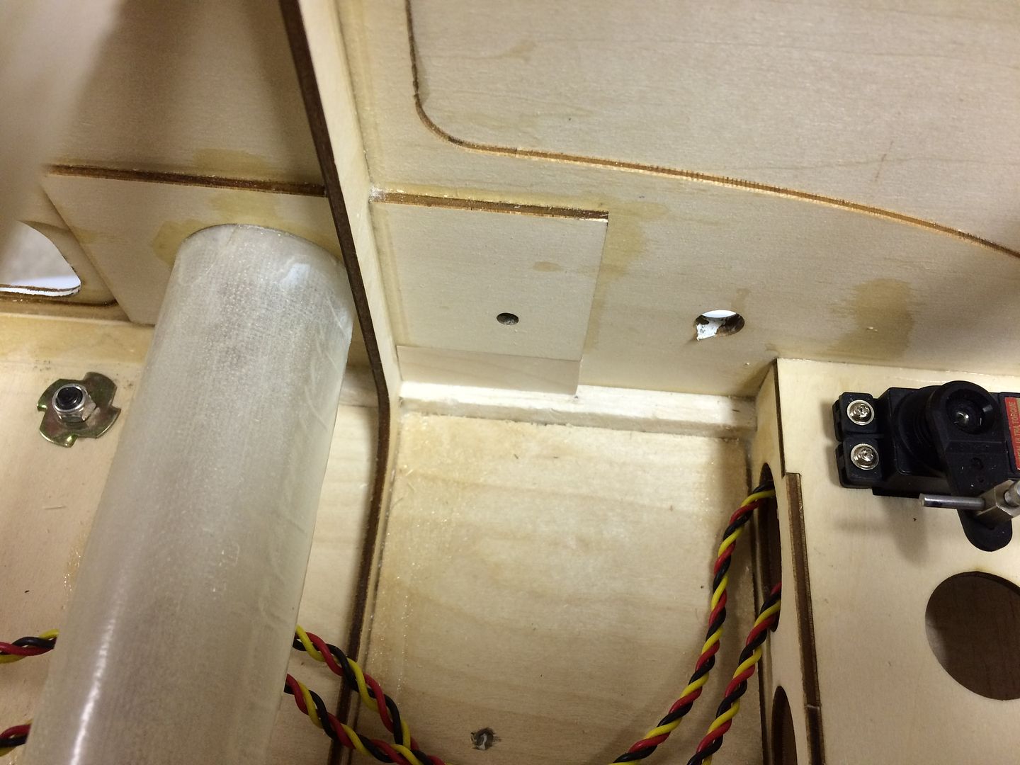
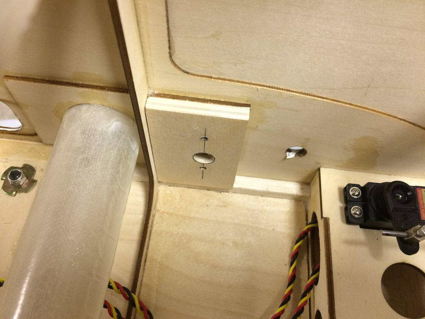
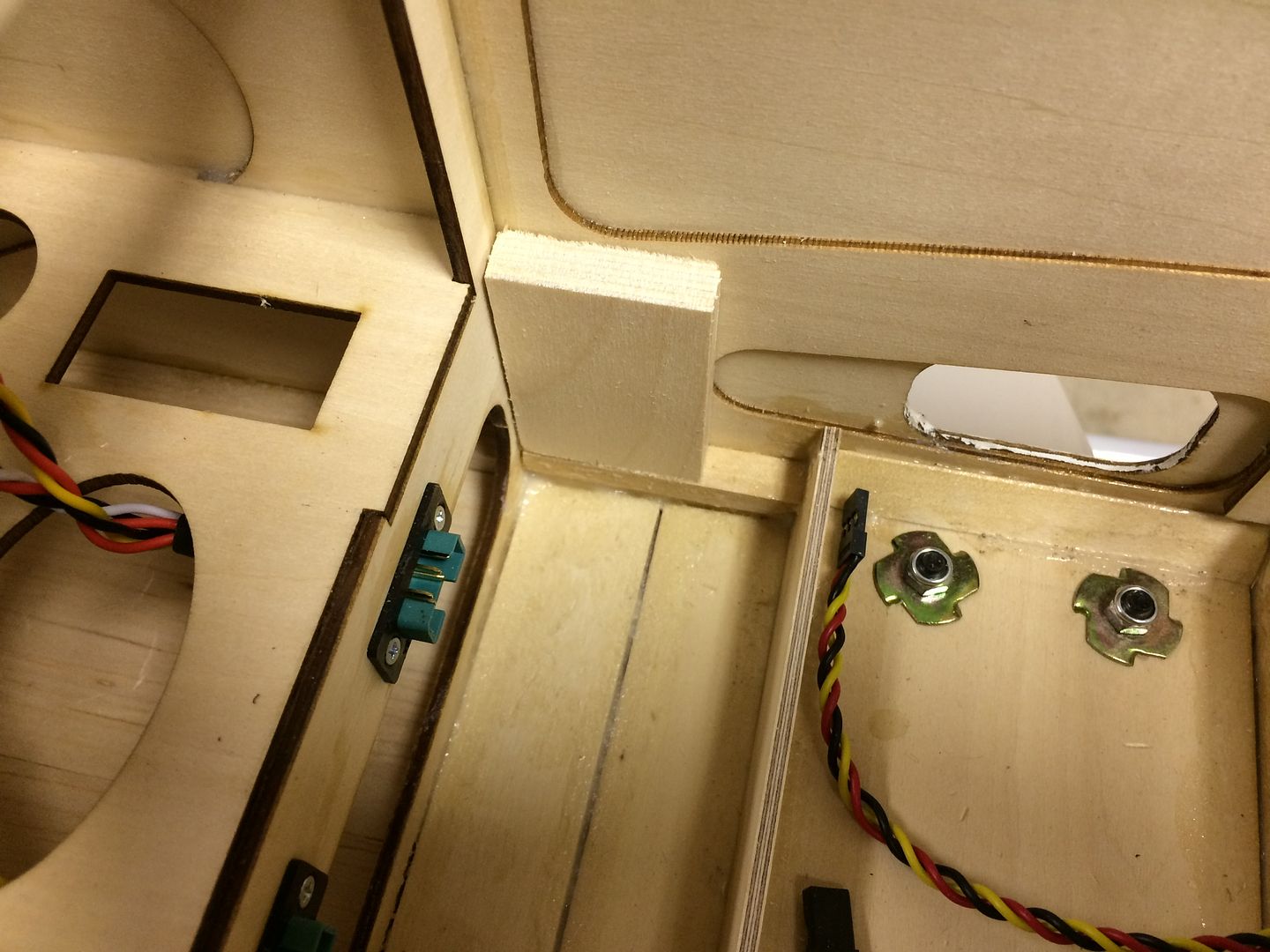
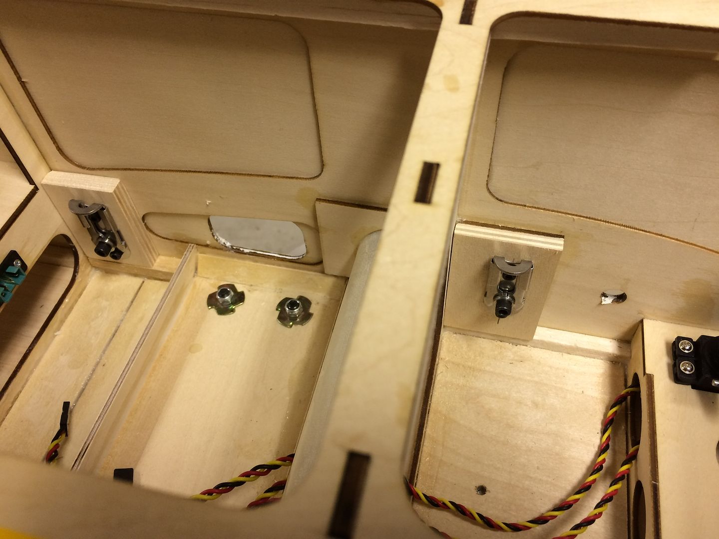
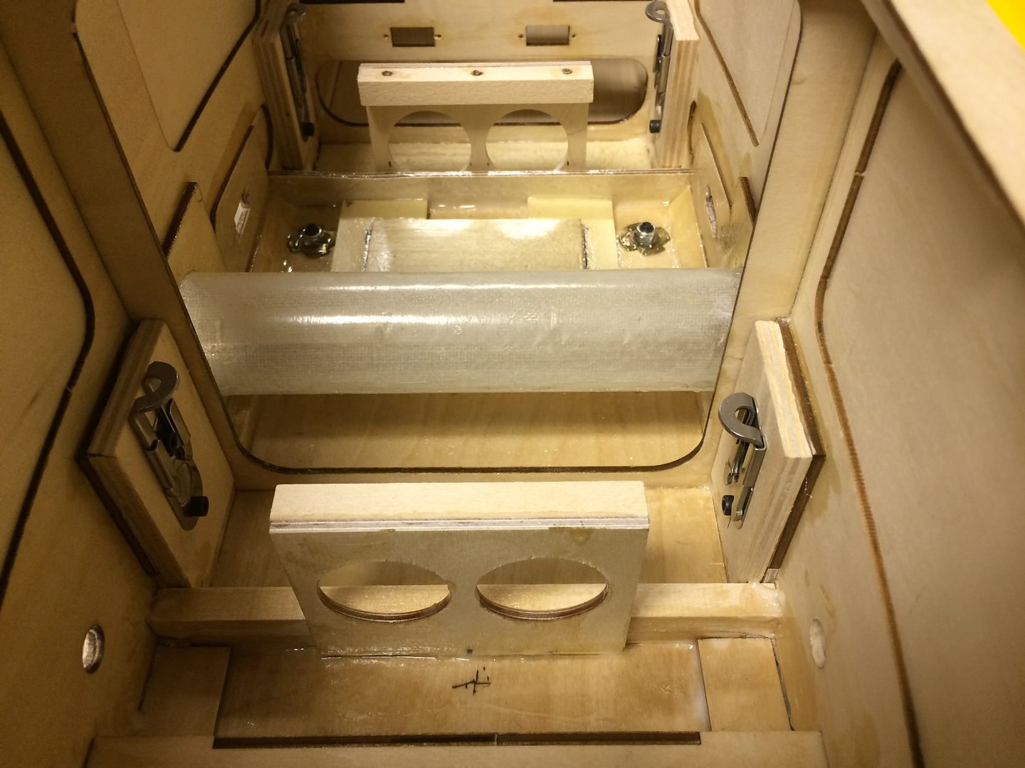
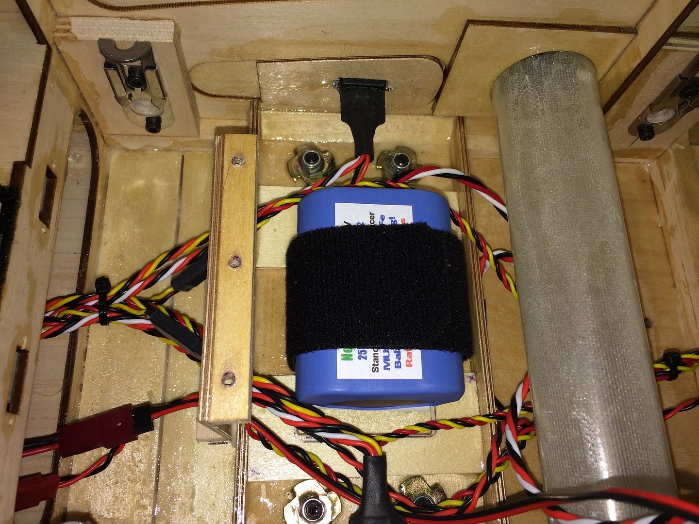
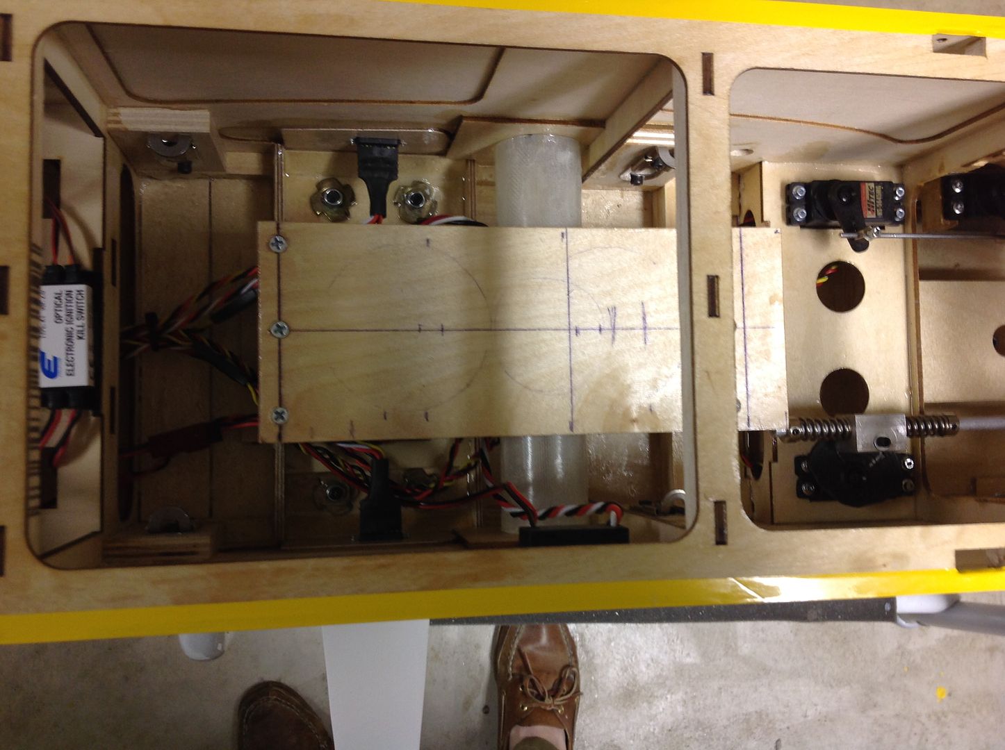
    If possible, we like to have nice straight pushrods on the throttle and choke. We were able to do just that on our Bidule 170 and decided to basically copy the same throttle and choke installation. Takes a little planning and test fitting, but we got the two servos tucked in and the rods run absolutely straight with not even a hint of binding.

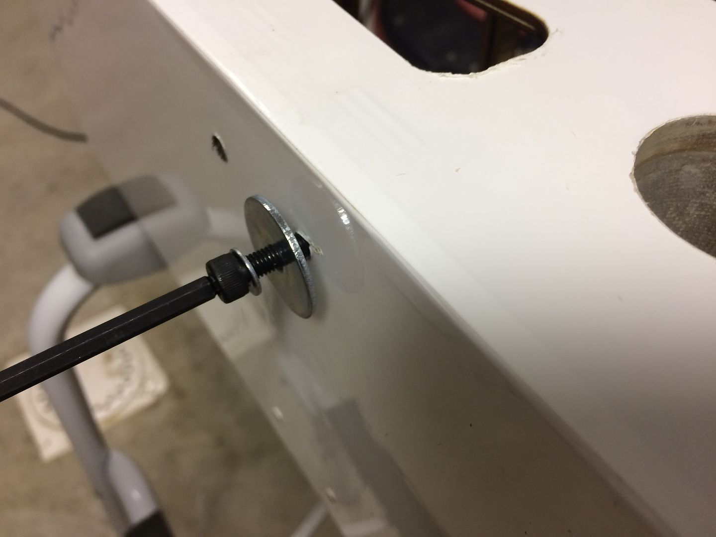
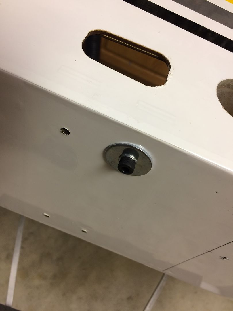
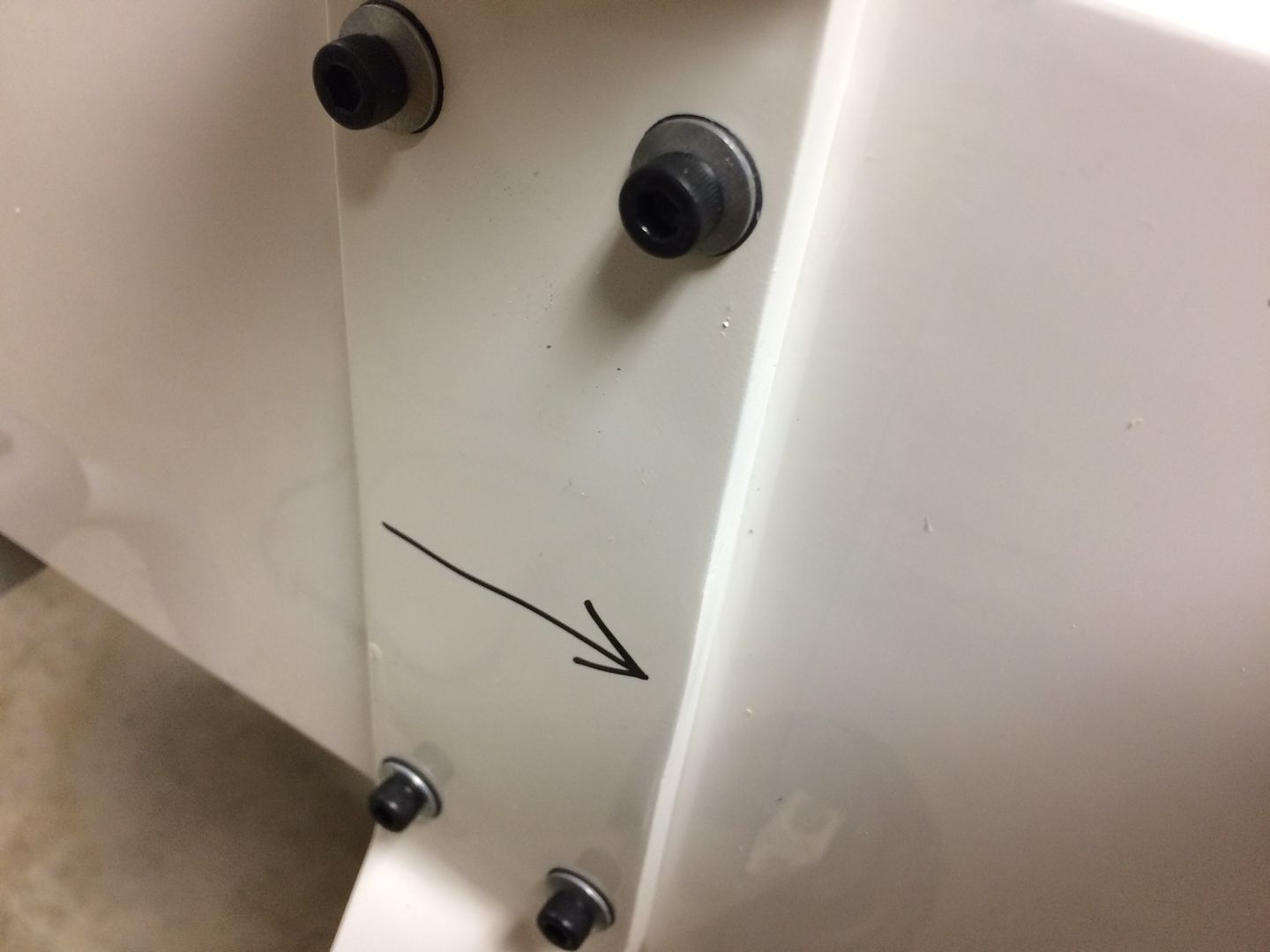
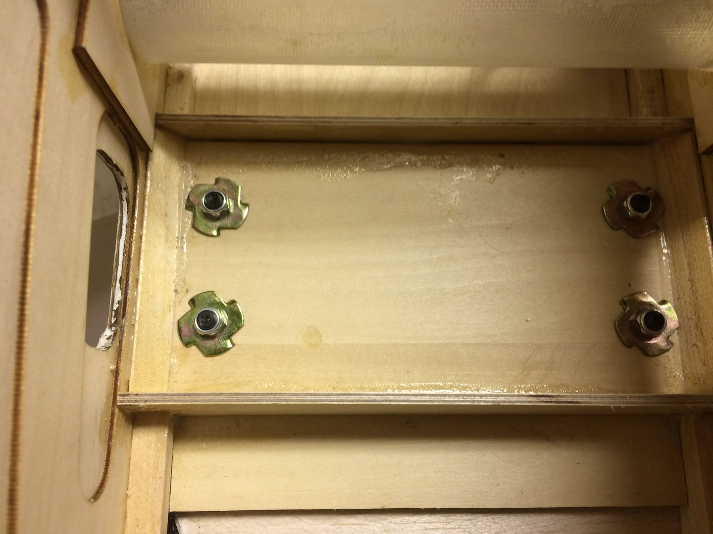
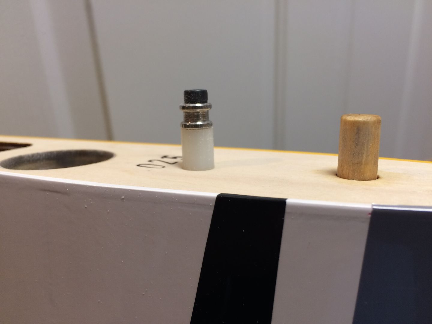
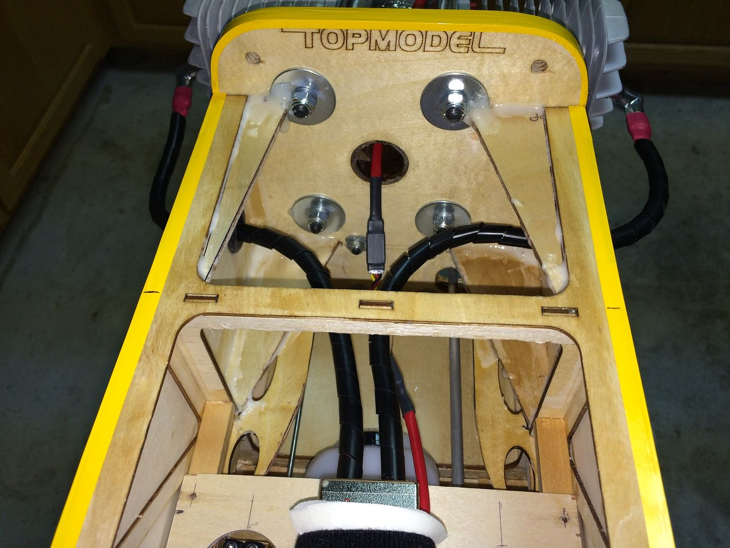
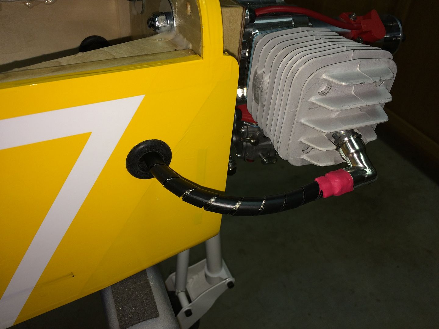
    Engine side of firewall view.


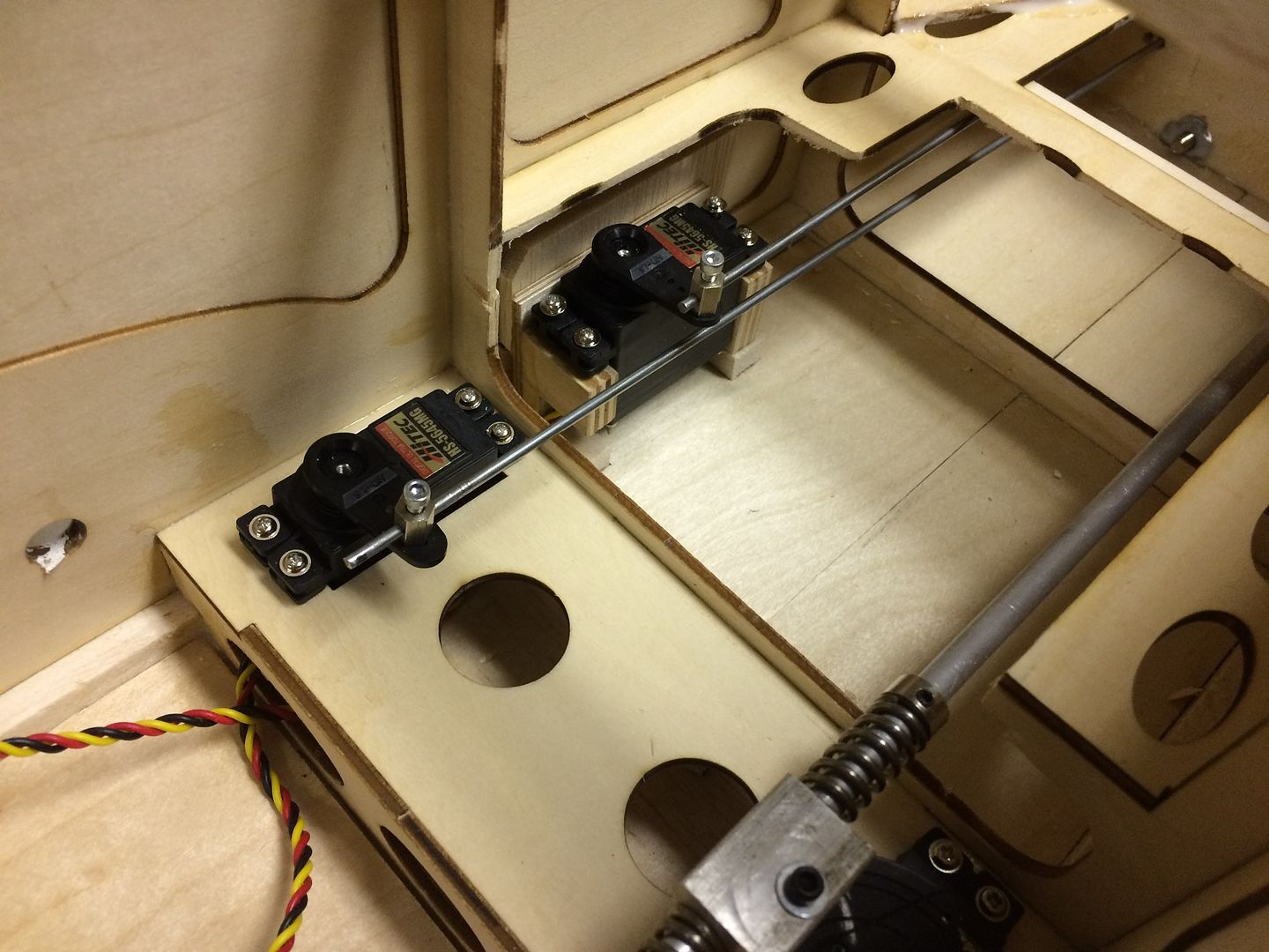
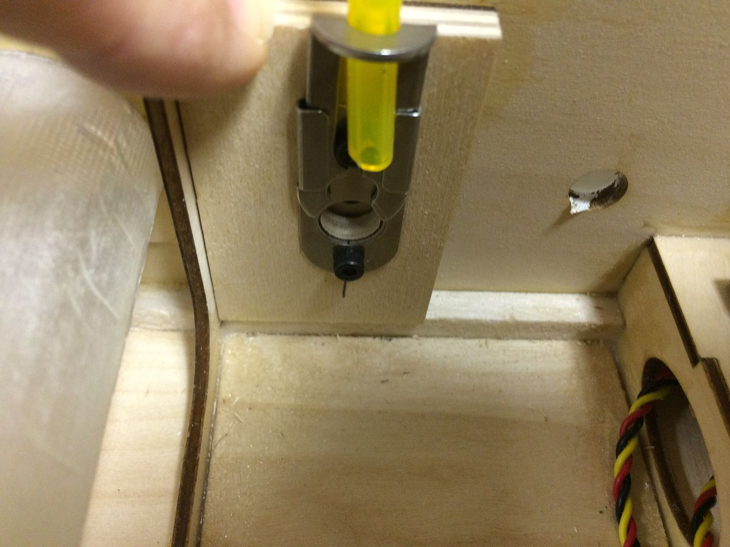
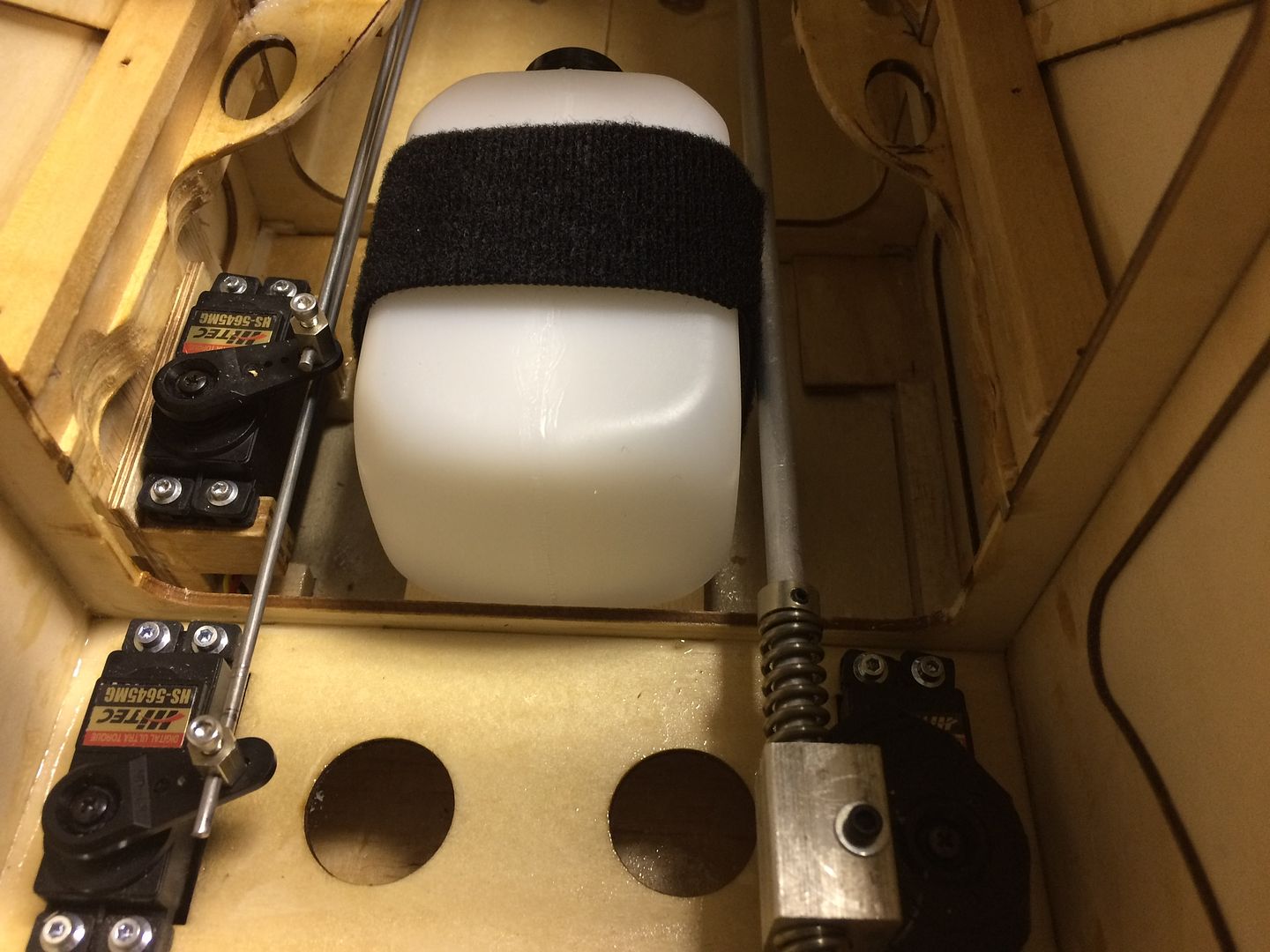
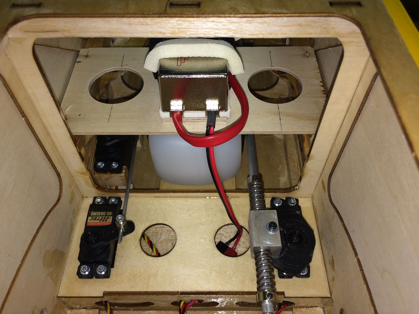
    Servo side of firewall view.
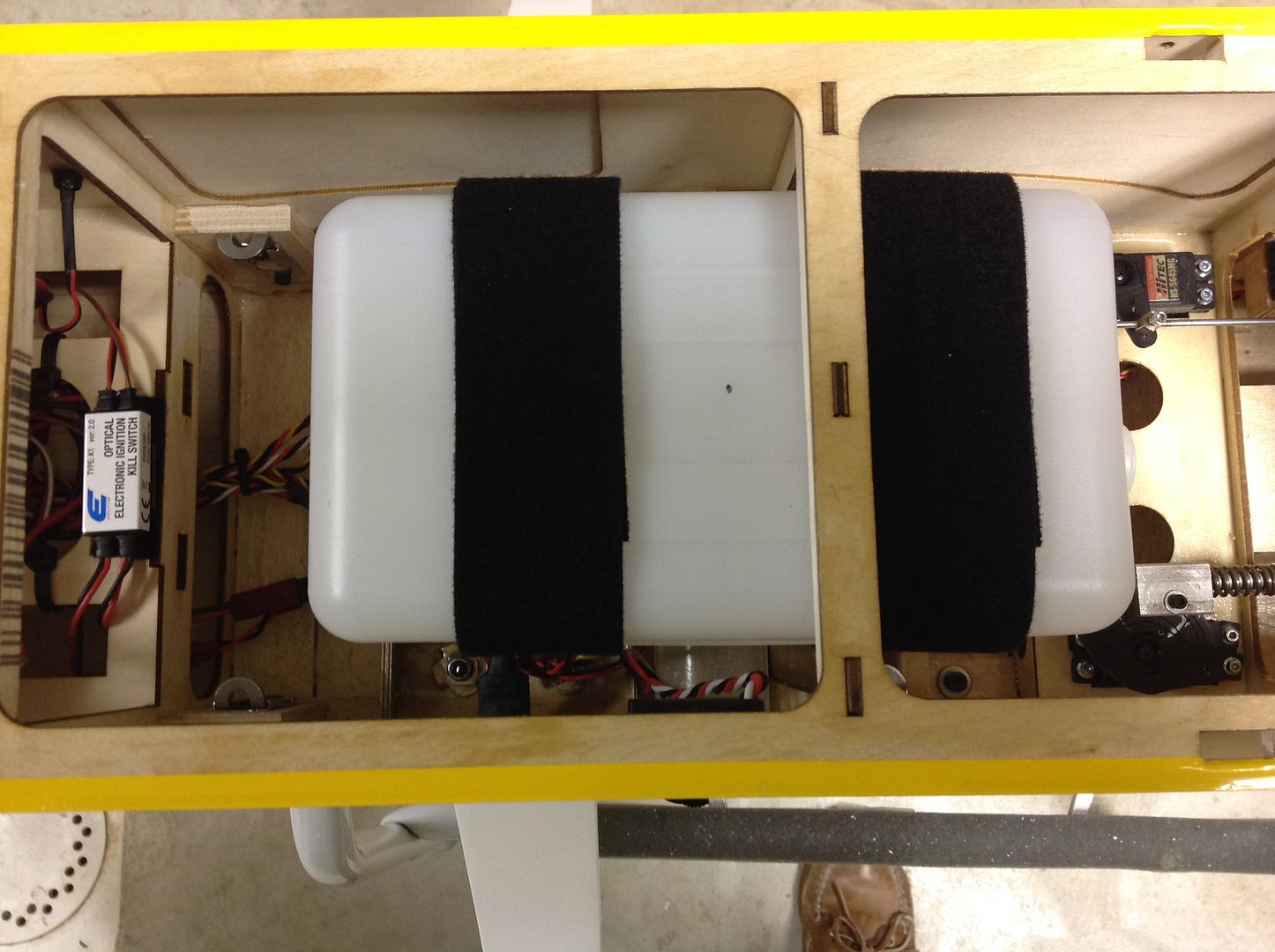
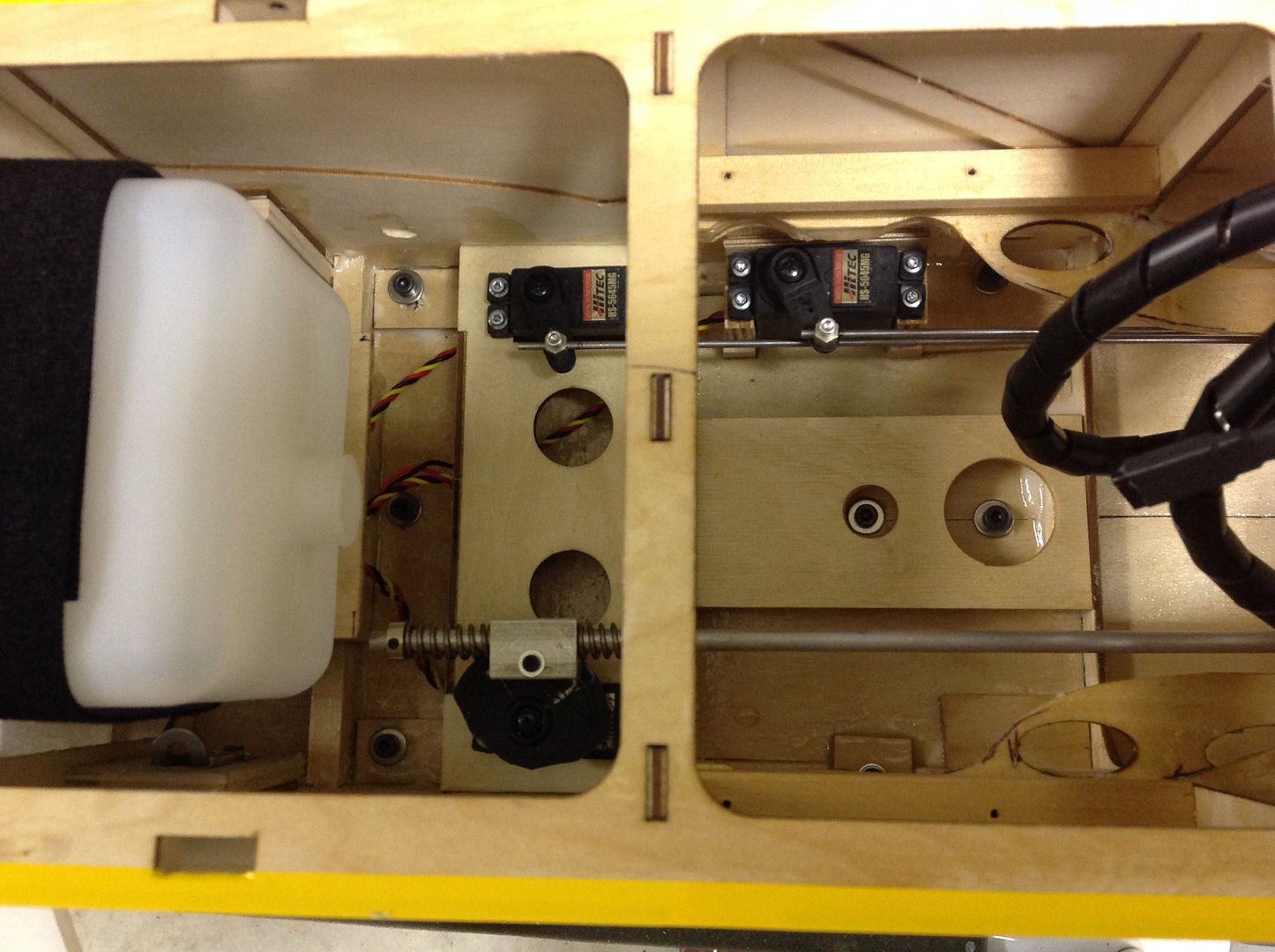
    A Site for Soar Eyes

    Comment


    • #47
      This is a big moment, all of the controls are now installed!

      Major things remaining are fuel tank and fuel line installation. The plan is to mount the tank on the CG just like we did on the Bidule 170.

      Next is to finish the installation of the headers and canisters. KS 86 canisters should be here early next week..

      Then the cowling can be cut and fit to the nose and the ignition can be installed and main gear can be attached.

      Add prop and spinner and then see if proper balance can be achieved by the location of the flight and ignition batteries.

      final step...wait for winter to be over so we can fly!
      A Site for Soar Eyes

      Comment


      • #48
        Hurry up and get it done Jim. That was we can put it on the shelf and wait....? Hmmm, kinda stinks doesn't it?

        Looks really good though.

        Len Buffinton
        Team Horizon Hobby

        Comment


        • Steve P
          Steve P commented
          Editing a comment
          When it's done, you will have a solid design theory. Proof will come when you replicate your experiment. Therefore, I will take this 111 so that you may start on another. There is a whole lotta building season left.

        • JimD
          JimD commented
          Editing a comment
          "There is a whole lotta building season left."

          My to do list:

          1) Finish second Bidule 170 which is partially constructed and all parts are in stock.
          2) Finish 1/3-scale Schweizer 2-33 which is partially constructed and all parts (accept covering) are in stock.
          3) Build twin Blaniks which are both NIB...all Spektrum radio gear in stock as well as all of the Aviation Concepts upgrade parts and tow releases
          4) Build another Bidule 111...uhh...what happened to all of that building season! LOL

          So did you get that shiny new DA from Chief on the Black Friday special?

        • Steve P
          Steve P commented
          Editing a comment
          I didn't Black Friday splurge since I can't decide if the Pawnee keeps that brand new 120 installed or, I sell th plane and move the motor to Bidule. Indecision!

      • #49
        Time to get the main gear mounted. The supplied hardware consists of M5 phillips head machine screws, plate washers, and lock nuts. My preference is to use cap head screws with bonded washers so we don't have metal tightened against the carbon gear. We also like T-nuts backed up with the lock nuts on the inside. Here is my M5 hardware, the bolts are 35mm length and have a smooth shank where they pass through the carbon gear.


        The holes in the gear plate and landing gear are slightly undersize for the M5 bolts. We used a 3/16" drill followed by a 13/64" drill to open up the holes in the plywood gear plate and the landing gear. The shoulder of the T-nuts is approximately 1/4", so we used tape as a depth gauge.


        Using a 12" long drill bit, the holes were carefully opened to the depth of the tape stop.


        The T-nuts were gently pushed into the holes and then drawn down tight using a short M5 bolt and fender washer to spread the force over a greater areaq.


        Then the gear was installed with the rack forward as previously discussed.Note the neoprene backed washers.


        As a finishing detail, the nylon insert lock nuts were tightened down against the T-nuts. This is how we did our Bidule 170 and it has worked extremely well for us.

        A Site for Soar Eyes

        Comment


        • #50
          Moving on to the ignition module mount, we again copied what we did on our Bidule 170. We fabricated plywood plate with another small piece on standoffs so a Velcro strap will wrap under it and then over the module. 1/4" foam acts as a vibration damper.


          Four screws hold it to the fuselage framework. We added basswood sticks under the thin internal plywood framework so the screws would have more substance to bite into. This entire unit can be removed if needed in order to service the throttle servo.

          A Site for Soar Eyes

          Comment


          • #51
            While we are waiting for the new canisters to arrive in the Big Brown Truck, we kept busy by making wing and stab bags. Check out the details HERE.

            We basically copied what we did for our Bidule 170.


            A Site for Soar Eyes

            Comment


            • #52
              When Asher Carmichael was building his Bidule 111, he found these slide latches at McMaster Carr and replaced the wing bolts with them.


              We ordered a set and have waffled on whether or not to use them. One issue was how to best mount them.

              After much thought, we came up with our solution to the mounting issue. Here is a picture essay of our plan:

              The fuselage side at the front wing bolt location is basically three thicknesses of 1/8" lite-ply. We cut a piece of scrap 1/8" plywood and fit it under the wing bolt doubler.


              We decided to use a piece of 1/4" AC plywood as the mounting surface for the slide latch and wanted this piece to extend all the way down to the bottom fuselage stringer.


              The fuselage thicness at the rear wing bolt location is two thicknesses of 1/8" lite-ply, so we decided to use 3/8" plywood for this location. First we added a short piece of 3/8" square basswood on top of the bottom fuselage stringer to help hold the 1/8" plywood gear plate cross member that we added earlier.


              Then we cut the 3/8" plywood (it needs a 2 degree angle on the bottom to fit properly.


              M3 bolts and blind nuts were just the right size to hold the slide latches to the plywood. We made a recess so the blind nuts would be flush with the back surfaces


              .

              A Site for Soar Eyes

              Comment


              • #53
                I have had great luck with these latches and they have been zero trouble since day one. Did you do anything so the latches will stay up while sliding the wing in? It quickly becomes a third hand necessary thing when sliding the wing on and having 2 latches... I loctited the heck out of the bolts holding the cylindrical clasp part and they have stayed put so far.

                Comment


                • #54
                  Hi Scot, I was going to be clever and embed a rare earth magnet above the latch to hold the slide open...but the slide is stainless steel. This is the simple fix for now, will just stick a piece of fuel tubing in one and hold the other open as I slide the wing on.

                  A Site for Soar Eyes

                  Comment


                  • #55
                    Doc, that's simple and effective. I put a shim between the slide and the bracket to add just enough friction to hold the slide in the raised position. Otherwise, like Stew and others, I have had no problems with these latches.

                    Comment


                    • #56
                      Hey guys.

                      After looking at your simple and elegant solutions to keeping the slide from falling down into the closed position during installation of the wing, I figured I should chime in with the "rude" solution.

                      Grab a pair of pliers and apply some pressure to the edge of the bent over tab. The drag you will apply is more than enough to do the job, of course, I did both edges for even wear

                      Worked like a charm.
                      Click image for larger version  Name:	IMG_4504.jpg Views:	1 Size:	7.4 KB ID:	14486

                      Len Buffinton
                      Team Horizon Hobby

                      Comment


                      • JimD
                        JimD commented
                        Editing a comment
                        So you are saying it was a tight squeeze installing your slide latches! LOL

                    • #57
                      The stock attachment system for the Bidule 111 wings is by way of two M4 nylon bolts per wing. We decided to locate the slide snaps so as to use the same location as the stock attachment points.The 3/8" diameter grooved fitting that the snap grasps needs to be attached to the wing so that they protrude just far enough into the fuselage that the slide snap can capture them. Using the plywood thicknesses mentioned above, we determined that we need a 1/2" extension to accomplish this.

                      The snap fittings are designed to be used with #8 screws. M4 bolts are just very slightly smaller than a #8 bolt, so instead of drilling out the blind nuts in the wings and tapping them with 8-32 threads, we decided to try using an M4 bolt with 1/2" nylon spacers.


                      Screwed into the wings, they look like this:


                      The holes in the fuselage must be enlarged to allow these 3/8" diameter parts to pass through.To do this without splintering the liteply fuselage sides, we stepped drilled the holes 1/64" bigger at a time.It really doesn't take all that long and the end result are nice clean holes that are well centered.


                      We did a final test fit and then used the slide snaps to hold our plywood mounts in place while the epoxy sets.


                      A battery mount for the ignition battery was fabricated on the landing gear plate. This is behind the CG and Under the main fuel tank.


                      Battery is held in place by the Velcro strap.

                      A Site for Soar Eyes

                      Comment


                      • #58
                        Even though the fuselage of the Bidule is wide open from the top, there are still a lot of things that need to fit into the space and need to be carefully planned out so that they do not interfere with one another.

                        When aerotowing at a busy event, it is good to be able to operate on a continuous basis of at least 45 minutes to one hour between refueling stops. This requires a big gas tank and the effect of that large tank on the CG needs to be considered.

                        The Bidule 111 instructions show the stock 50 once tank mounted well forward of the CG and clear of the wing bolts. Our preference is to have the main tank located directly over the CG and then place a header tank forward of that. This puts the main tank right over the wing bolt locations and then either the tank has to be movable or else the wing bolts need to be replaced with slide latches. Obviously, we opted for the slide latches.

                        With the tank semi-permanently mounted, we discovered that access to the electrical connections for the wings was going to be tricky...the solution was to relocate the Multiplex connectors from the internal stock location to the opening in the side of the fuselage where the wing servo extension would enter the fuselage. Mounting plates for the Multiplex connectors were added along with the fuel tank platform mounts.


                        The entire floor area from the nose to the back of the radio compartment was fuel-proofed with epoxy thinned with 91% isopropyl alcohol. Once cured, we began the process of installing the servos, switches, batteries, and wiring. The ignition battery is located on the landing gear plate under the fuel tank just behind the CG. The Multiplex connectors are to either side of the battery.


                        Here you can see the external view of the Multiplex connectors and the location of the switches/charge ports for the right side receiver and the ignition.


                        The receivers, receiver batteries, switches, and ignition kill are located in the aft section of the fuselage (all behind the CG).


                        We placed the 10 once header tank between the throttle & choke servos on the left and the steering servo on the right. Snug fit, but works without issues. The steering rod does NOT rub the tank even though it looks like it does in this picture.


                        The ignition module sits on a removable platform above the tank.


                        The ignition wires are routed forward and out through the fuselage sides. Nice installation with no sharp kinks in the cables.


                        We got rubber grommets from McMaster Carr and black vinyl electrical wire spiral wrap from Lowe's ...adds a nice finishing touch to the ignition wires and exits points.


                        Last edited by JimD; 12-24-2016, 03:59 PM.
                        A Site for Soar Eyes

                        Comment


                        • #59
                          The main fuel tank support platform is attached to the support bases by screws so it can be removed if necessary.


                          The tank is held to the platform with Velcro straps.


                          The header tank platform is epoxied in place, but we drilled access holes to get to the canister mount attachment hardware. The rear canister mounts attach just in front of the main tank (note three lock nuts visible on floor. The forward canister mounts are staggered and the center attachment points can be seen through the holes in the tank platform.


                          Here is what the canisters and their mounts looks like. Note that rear attachment has added nylon spacer to allow the canisters to follow the taper of the floor of the nose area.


                          In order to keep the header pipes equal and optimum length, the canisters are staggered by the amount of the offset between the right and left cylinders of the engine.

                          A Site for Soar Eyes

                          Comment


                          • #60
                            I used stock 90mm drop headers on my Bidule 170, but had to add about 2" to the length between the mounting flange and 90 degree bend. The pipe was cut in half 1" below the flange and then the 2" section was welded in between to increase the length. I planned to do the same thing on the Bidule 111, but noticed that the 90mm drop headers only needed an additional 3/4" to work, so instead of cutting the pipe and welding in the 3/4" extension we are trying another route.

                            Placing a call to Gunny at Aviation Concepts, we were able to get custom designed extensions and gaskets that will simply bolt on between the header flange and engine exhaust outlet. These were water-jet cut from 3/4" aircraft grade aluminum plate. Gunny added cooling fins just to make them look extra cool...well, made cool in more than one way!

                            Here is a picture fresh from the fabricator. I should have them in my hands Friday, so we will see if this plan works as good as I think it should.

                            A Site for Soar Eyes

                            Comment

                            Working...
                            X